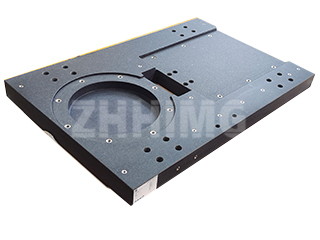
The machine bed serves as the core foundational component of any mechanical equipment, and its assembly process is a crucial step that dictates structural rigidity, geometric accuracy, and long-term dynamic stability. Far from a simple bolted assembly, constructing a precision machine bed is a multi-stage system engineering challenge. Every step—from initial referencing to final functional tuning—demands synergistic control of multiple variables to ensure the bed maintains stable performance under complex operational loads.
The Groundwork: Initial Referencing and Leveling
The assembly process begins with establishing an absolute reference plane. This is typically achieved using a high-precision granite surface plate or a laser tracker as the global benchmark. The base of the machine bed is initially leveled using support leveling wedges (chock blocks). Specialized measuring tools, such as electronic levels, are used to adjust these supports until the parallelism error between the bed’s guideway surface and the reference plane is minimized.
For extremely large beds, a phased leveling strategy is employed: the center support points are fixed first, and leveling progresses outwards towards the ends. Continuous monitoring of the guideway straightness using a dial indicator is essential to prevent sag in the middle or warping at the edges due to the component’s self-weight. Attention is also paid to the material of the support wedges; cast iron is often chosen for its similar thermal expansion coefficient to the machine bed, while composite pads are utilized for their superior damping properties in vibration-sensitive applications. A thin film of specialized anti-seize lubricant on the contact surfaces minimizes frictional interference and prevents micro-slippage during the long-term settling phase.
Precision Integration: Assembling the Guideway System
The guideway system is the core component responsible for linear motion, and its assembly accuracy is directly proportional to the equipment’s machining quality. After preliminary fixing with locating pins, the guideway is clamped, and the pre-tension force is meticulously applied using press plates. The pre-tensioning process must adhere to a “uniform and progressive” principle: bolts are tightened incrementally from the center of the guideway outwards, applying only partial torque in each round until the design specification is met. This strict process prevents localized stress concentration that could induce guideway bowing.
A critical challenge is adjusting the running clearance between the slider blocks and the guideway. This is achieved through a combined feeler gauge and dial indicator measurement method. By inserting feeler gauges of varying thicknesses and measuring the resulting slider displacement with a dial indicator, a clearance-displacement curve is generated. This data guides the micro-adjustment of eccentric pins or wedge blocks on the slider’s side, ensuring uniform clearance distribution. For ultra-precision beds, a nano-lubrication film may be applied to the guideway surface to lower the friction coefficient and enhance motion smoothness.
Rigid Connection: Spindle Headstock to Bed
The connection between the spindle headstock, the heart of power output, and the machine bed demands a careful balance of rigid load transmission and vibration isolation. The cleanliness of the mating surfaces is paramount; contact areas must be meticulously wiped with a dedicated cleaning agent to remove all contaminants, followed by the application of a thin layer of specialized analytical-grade silicone grease to enhance contact stiffness.
The bolt tightening sequence is critical. A symmetrical pattern, typically “expanding outward from the center,” is used. Bolts in the center region are pre-tightened first, with the sequence radiating outwards. Stress release time must be factored in after each tightening round. For critical fasteners, an ultrasonic bolt preload detector is used to monitor the axial force in real-time, ensuring uniform stress distribution across all bolts and preventing localized loosening that could trigger unwanted vibrations.
Post-connection, a modal analysis is performed. An exciter induces vibrations at specific frequencies on the headstock, and accelerometers collect response signals across the machine bed. This confirms that the base’s resonant frequencies are sufficiently decoupled from the system’s operating frequency range. If resonance risk is detected, mitigation involves installing damping shims at the interface or fine-tuning bolt preload to optimize the vibration transmission path.
Final Verification and Compensation of Geometric Accuracy
Once assembled, the machine bed must undergo a comprehensive final geometric inspection. A laser interferometer measures straightness, using mirror assemblies to amplify tiny deviations over the guideway’s length. An electronic level system maps the surface, establishing a 3D profile from multiple measurement points. A autocollimator checks perpendicularity by analyzing the shift of a light spot reflected from a precision prism.
Any detected out-of-tolerance deviations require precise compensation. For localized straightness errors on the guideway, the supporting wedge surface can be corrected via hand scraping. A developer agent is applied to the high points, and friction from the moving slider reveals the contact pattern. The high points are meticulously scraped to gradually achieve the theoretical contour. For large beds where scraping is impractical, hydraulic compensation technology can be employed. Miniature hydraulic cylinders are integrated into the support wedges, allowing non-destructive adjustment of the wedge thickness by modulating the oil pressure, achieving accuracy without physical material removal.
Unloaded and Loaded Commissioning
The final phases involve commissioning. During the unloaded debugging stage, the bed operates under simulated conditions while an infrared thermal camera monitors the headstock’s temperature curve and pinpoints localized hot spots for potential cooling channel optimization. Torque sensors monitor motor output fluctuations, allowing for adjustment of the drive chain clearances. The loaded debugging phase gradually increases the cutting force, observing the bed’s vibration spectrum and the quality of the machined surface finish to confirm the structural rigidity meets design specifications under real-world stress.
The assembly of a machine bed component is a systematic integration of multi-step, precision-controlled processes. Through strict adherence to assembly protocols, dynamic compensation mechanisms, and thorough verification, ZHHIMG ensures the machine bed maintains micron-level accuracy under complex loads, providing the unshakeable foundation for world-class equipment operation. As intelligent detection and self-adaptive adjustment technologies continue to advance, future machine bed assembly will become increasingly predictive and autonomously optimized, pushing mechanical manufacturing into new regimes of precision.
Post time: Nov-14-2025

