
In the world of precision manufacturing, particularly in aerospace and high-precision machining sectors, error control is not merely important—it is existential. A single micron of deviation can render a component useless, compromise safety-critical systems, or result in catastrophic failure in aerospace applications. Modern CNC machines can achieve positioning accuracies of ±1-5 μm, but translating this machine capability into part accuracy requires a comprehensive understanding of error sources and systematic control strategies.
This guide presents 8 critical factors that influence machining accuracy, spanning from raw material selection to advanced process optimization. By systematically addressing each factor, precision manufacturers can minimize errors, reduce scrap rates, and deliver components that meet the most stringent specifications.
The Error Control Challenge in Precision Machining
Before diving into specific factors, it is essential to understand the magnitude of the challenge:
Modern Tolerance Requirements:
- Aerospace Turbine Components: ±0.005 mm (5 μm) profile tolerance
- Medical Implants: ±0.001 mm (1 μm) dimensional tolerance
- Optical Components: ±0.0005 mm (0.5 μm) surface form error
- Precision Bearings: ±0.0001 mm (0.1 μm) roundness requirement
Machine Capability vs. Part Accuracy:
Even with state-of-the-art CNC equipment achieving positioning repeatability of ±1 μm, actual part accuracy depends on systematic control of thermal, mechanical, and process-induced errors that can easily exceed 10-20 μm if left unaddressed.
Even with state-of-the-art CNC equipment achieving positioning repeatability of ±1 μm, actual part accuracy depends on systematic control of thermal, mechanical, and process-induced errors that can easily exceed 10-20 μm if left unaddressed.
Factor 1: Material Selection and Properties
The foundation of precision machining begins long before the first cut—during material selection. Different materials exhibit vastly different machining characteristics that directly influence achievable tolerances.
Material Properties Affecting Machining Accuracy
| Material Property | Impact on Machining | Ideal Materials for Precision |
|---|---|---|
| Thermal Expansion | Dimensional changes during machining | Invar (1.2×10⁻⁶/°C), Titanium (8.6×10⁻⁶/°C) |
| Hardness | Tool wear and deflection | Hardened steels (HRC 58-62) for wear resistance |
| Modulus of Elasticity | Elastic deformation under cutting forces | High-modulus alloys for rigidity |
| Thermal Conductivity | Heat dissipation and thermal distortion | Copper alloys for high thermal conductivity |
| Internal Stress | Part distortion after machining | Stress-relieved alloys, aged materials |
Common Precision Machining Materials
Aerospace Aluminum Alloys (7075-T6, 7050-T7451):
- Advantages: High strength-to-weight ratio, excellent machinability
- Challenges: High thermal expansion (23.6×10⁻⁶/°C), tendency for work hardening
- Best Practices: Sharp tools, high coolant flow, thermal management
Titanium Alloys (Ti-6Al-4V, Ti-6Al-2Sn-4Zr-6Mo):
- Advantages: Exceptional strength at high temperatures, corrosion resistance
- Challenges: Low thermal conductivity causes heat buildup, work hardening, chemical reactivity
- Best Practices: Low cutting speeds, high feed rates, specialized tooling
Stainless Steels (17-4 PH, 15-5 PH):
- Advantages: Precipitation-hardening for consistent properties, good corrosion resistance
- Challenges: High cutting forces, rapid tool wear, work hardening
- Best Practices: Rigid setups, positive rake tools, adequate tool life management
Superalloys (Inconel 718, Waspaloy):
- Advantages: Exceptional high-temperature strength, creep resistance
- Challenges: Extremely difficult to machine, high heat generation, rapid tool wear
- Best Practices: Interrupted cutting strategies, advanced tool materials (PCBN, ceramic)
Critical Material Selection Considerations:
- Stress State: Choose materials with minimal internal stress or incorporate stress-relief operations
- Machinability Ratings: Consider standardized machinability indices when selecting materials
- Batch Consistency: Ensure material properties are consistent across production batches
- Certification Requirements: Aerospace applications require traceability and certification (NADCAP, AMS specifications)
Factor 2: Heat Treatment and Stress Management
Internal stresses in metal components are a primary source of post-machining distortion, often causing parts that measured within tolerance on the machine to deviate after unclamping or during service.
Sources of Internal Stress
Residual Stresses from Manufacturing:
- Casting and Forging: Rapid cooling during solidification creates thermal gradients
- Cold Working: Plastic deformation induces stress concentrations
- Heat Treatment: Non-uniform heating or cooling leaves residual stresses
- Machining Itself: Cutting forces create localized stress fields
Heat Treatment Strategies for Precision
Stress Relieving (650-700°C for steels, 2-4 hours):
- Reduces internal stresses by allowing atomic rearrangement
- Minimal impact on mechanical properties
- Performed before rough machining or between roughing and finishing
Annealing (700-800°C for steels, 1-2 hours per inch thickness):
- Complete stress relief and recrystallization
- Reduces hardness for improved machinability
- May require re-heat treatment after machining to restore properties
Solution Annealing (for precipitation-hardening alloys):
- Dissolves precipitates, creates uniform solid solution
- Enables uniform aging response
- Essential for aerospace titanium and superalloy components
Cryogenic Treatment (-195°C liquid nitrogen, 24 hours):
- Transforms retained austenite to martensite in steels
- Improves dimensional stability and wear resistance
- Particularly effective for precision tooling and components
Practical Heat Treatment Guidelines
| Application | Recommended Treatment | Timing |
|---|---|---|
| Precision Shafts | Stress relieve + Normalize | Before rough machining |
| Aerospace Titanium | Solution anneal + Age | Before rough machining |
| Hardened Steel Tools | Quench + Temper + Cryogenic | Before finish grinding |
| Large Castings | Anneal (slow cool) | Before any machining |
| Thin-Walled Parts | Stress relieve (multiple) | Between machining passes |
Critical Considerations:
- Thermal Uniformity: Ensure uniform heating and cooling to prevent new stresses
- Fixturing: Parts must be supported to prevent distortion during heat treatment
- Process Control: Strict temperature control (±10°C) and documented procedures
- Verification: Use residual stress measurement techniques (X-ray diffraction, hole-drilling) for critical components
Factor 3: Tool Selection and Tooling Systems
The cutting tool is the interface between the machine and the workpiece, and its selection profoundly influences machining accuracy, surface finish, and process stability.
Tool Material Selection
Carbide Grades:
- Fine-Grained Carbide (WC-Co): General-purpose machining, good wear resistance
- Coated Carbide (TiN, TiCN, Al2O3): Extended tool life, reduced built-up edge formation
- Submicron Carbide: Ultra-fine grain (0.2-0.5 μm) for high-precision finishing
Advanced Tool Materials:
- Polycrystalline Cubic Boron Nitride (PCBN): Hardened steel machining, 4000-5000 HV
- Polycrystalline Diamond (PCD): Non-ferrous metals, ceramics, 5000-6000 HV
- Ceramic (Al2O3, Si3N4): High-speed machining of cast iron and superalloys
- Cermet (Ceramic-Metal): Precision finishing of steels, excellent surface finish
Tool Geometry Optimization
Critical Geometric Parameters:
- Rake Angle: Affects cutting forces and chip formation
- Positive rake (5-15°): Lower cutting forces, better surface finish
- Negative rake (-5 to -10°): Stronger cutting edge, better for hard materials
- Clearance Angle: Prevents rubbing, typically 5-8° for finishing
- Lead Angle: Affects surface finish and chip thickness
- Edge Preparation: Honed edges for strength, sharp edges for precision
Precision Tooling Considerations:
- Tool Holder Rigidity: Hydrostatic chucks, shrink-fit holders for maximum stiffness
- Tool Runout: Must be <5 μm for precision applications
- Tool Length Minimization: Shorter tools reduce deflection
- Balance: Critical for high-speed machining (ISO 1940 G2.5 or better)
Tool Life Management Strategies
Wear Monitoring:
- Visual Inspection: Check for flank wear, chipping, built-up edge
- Force Monitoring: Detect increasing cutting forces
- Acoustic Emission: Detect tool wear and breakage in real-time
- Surface Quality Degradation: Warning sign of tool wear
Tool Change Strategies:
- Time-Based: Replace after predetermined cutting time (conservative)
- Condition-Based: Replace based on wear indicators (efficient)
- Adaptive Control: Real-time adjustment based on sensor feedback (advanced)
Precision Tooling Best Practices:
- Presets and Offsets: Measure tools offline to reduce setup time
- Tool Management Systems: Track tool life, usage, and location
- Tool Coating Selection: Match coating to material and application
- Tool Storage: Proper storage to prevent damage and corrosion
Factor 4: Fixturing and Workholding Strategies
Workholding is often an overlooked source of machining errors, yet improper fixturing can introduce substantial distortion, vibration, and positional inaccuracies.
Fixturing Error Sources
Clamping-Induced Distortion:
- Excessive clamping forces deform thin-walled components
- Asymmetric clamping creates uneven stress distribution
- Repeated clamping/unclamping causes cumulative deformation
Positioning Errors:
- Locating element wear or misalignment
- Workpiece surface irregularities at contact points
- Inadequate datum establishment
Vibration and Chatter:
- Insufficient fixture rigidity
- Improper damping characteristics
- Natural frequency excitation
Advanced Fixturing Solutions
Zero-Point Clamping Systems:
- Rapid, repeatable workpiece positioning
- Consistent clamping forces
- Reduced setup time and error
Hydraulic and Pneumatic Fixtures:
- Precise, repeatable clamping force control
- Automated clamping sequences
- Integrated pressure monitoring
Vacuum Chucks:
- Uniform clamping force distribution
- Ideal for thin, flat workpieces
- Minimal workpiece distortion
Magnetic Workholding:
- Non-contact clamping for ferrous materials
- Uniform force distribution
- Access to all sides of workpiece
Fixturing Design Principles
3-2-1 Locating Principle:
- Primary Datum (3 points): Establishes the primary plane
- Secondary Datum (2 points): Establishes orientation on the second plane
- Tertiary Datum (1 point): Establishes final position
Precision Fixturing Guidelines:
- Minimize Clamping Forces: Use minimum force required to prevent movement
- Distribute Loads: Use multiple contact points to distribute forces evenly
- Allow for Thermal Expansion: Avoid over-constraining the workpiece
- Use Sacrificial Plates: Protect fixture surfaces and reduce wear
- Design for Accessibility: Ensure tool access and measurement access
Fixturing Error Prevention:
- Pre-machining: Establish datums on rough surfaces before precision operations
- Sequential Clamping: Use controlled clamping sequences to minimize distortion
- Stress Relief: Allow workpiece relaxation between operations
- In-Process Measurement: Verify dimensions during machining, not just after
Factor 5: Cutting Parameters Optimization
Cutting parameters—speed, feed, depth of cut—must be optimized not just for productivity, but for dimensional accuracy and surface finish.
Cutting Speed Considerations
Speed Selection Principles:
- Higher Speeds: Better surface finish, lower cutting forces per tooth
- Lower Speeds: Reduced heat generation, less tool wear
- Material-Specific Ranges:
- Aluminum: 200-400 m/min
- Steel: 80-150 m/min
- Titanium: 30-60 m/min
- Superalloys: 20-40 m/min
Speed Accuracy Requirements:
- Precision Machining: ±5% of programmed speed
- Ultra-Precision: ±1% of programmed speed
- Constant Surface Speed: Essential for maintaining consistent cutting conditions
Feed Rate Optimization
Feed Calculation:
Feed per tooth (fz) = Feed rate (vf) / (Number of teeth × Spindle speed)Feed Considerations:
- Coarse Feed: Material removal, roughing operations
- Fine Feed: Surface finish, precision finishing
- Optimal Range: 0.05-0.20 mm/tooth for steel, 0.10-0.30 mm/tooth for aluminum
Feed Accuracy:
- Positioning Accuracy: Must match machine capability
- Feed Smoothing: Advanced control algorithms reduce jerk
- Ramp-Up/Ramp-Down: Controlled acceleration/deceleration to prevent errors
Depth of Cut and Stepover
Axial Depth of Cut (ap):
- Roughing: 2-5 × tool diameter
- Finishing: 0.1-0.5 × tool diameter
- Light Finishing: 0.01-0.05 × tool diameter
Radial Depth of Cut (ae):
- Roughing: 0.5-0.8 × tool diameter
- Finishing: 0.05-0.2 × tool diameter
Optimization Strategies:
- Adaptive Control: Real-time adjustment based on cutting forces
- Trochoidal Milling: Reduces tool load, improves surface finish
- Variable Depth Optimization: Adjust based on geometry changes
Cutting Parameter Impact on Accuracy
| Parameter | Low Values | Optimal Range | High Values | Effect on Accuracy |
|---|---|---|---|---|
| Cutting Speed | Built-up edge, poor finish | Material-specific range | Rapid tool wear | Variable |
| Feed Rate | Rubbing, poor finish | 0.05-0.30 mm/tooth | Chatter, deflection | Negative |
| Depth of Cut | Inefficient, tool rubbing | Geometry-dependent | Tool breakage | Variable |
| Stepover | Efficient, scalloped surface | 10-50% tool diameter | Tool load, heat | Variable |
Cutting Parameter Optimization Process:
- Start with Manufacturer Recommendations: Use tool manufacturer’s baseline parameters
- Conduct Test Cuts: Evaluate surface finish and dimensional accuracy
- Measure Forces: Use dynamometers or current monitoring
- Optimize Iteratively: Adjust based on results, monitor tool wear
- Document and Standardize: Create proven process parameters for repeatability
Factor 6: Toolpath Programming and Machining Strategies
The way cutting paths are programmed directly influences machining accuracy, surface finish, and process efficiency. Advanced toolpath strategies can minimize errors that are inherent in conventional approaches.
Toolpath Error Sources
Geometric Approximations:
- Linear interpolation of curved surfaces
- Chord deviation from ideal profiles
- Faceting errors in complex geometries
Directional Effects:
- Climb vs. conventional cutting
- Cutting direction relative to material grain
- Entry and exit strategies
Toolpath Smoothing:
- Jerk and acceleration effects
- Corner rounding
- Velocity changes at path transitions
Advanced Toolpath Strategies
Trochoidal Milling:
- Advantages: Reduced tool load, constant engagement, extended tool life
- Applications: Slot milling, pocket machining, difficult-to-cut materials
- Accuracy Impact: Improved dimensional consistency, reduced deflection
Adaptive Machining:
- Real-Time Adjustment: Modify feed based on cutting forces
- Tool Deflection Compensation: Adjust path to account for tool bending
- Vibration Avoidance: Skip problematic frequencies
High-Speed Machining (HSM):
- Light Cuts, High Feeds: Reduces cutting forces and heat generation
- Smoother Surfaces: Better surface finish, reduced finishing time
- Accuracy Improvement: Consistent cutting conditions throughout operation
Spiral and Helical Toolpaths:
- Continuous Engagement: Avoids entry/exit errors
- Smooth Transitions: Reduces vibration and chatter
- Improved Surface Finish: Consistent cutting direction
Precision Machining Strategies
Roughing vs. Finishing Separation:
- Roughing: Remove bulk material, prepare datum surfaces
- Semi-Finishing: Get close to final dimensions, relieve residual stress
- Finishing: Achieve final tolerance, surface finish requirements
Multi-Axis Machining:
- 5-Axis Advantages: Single setup, better tool approach, shorter tools
- Complex Geometry: Ability to machine undercut features
- Accuracy Considerations: Increased kinematic errors, thermal growth
Finishing Strategies:
- Ball Nose End Mills: For sculptured surfaces
- Fly Cutting: For large flat surfaces
- Diamond Turning: For optical components and ultra-precision
- Honing/Lapping: For final surface refinement
Toolpath Optimization Best Practices
Geometric Accuracy:
- Tolerance-Based: Set appropriate chord tolerance (typically 0.001-0.01 mm)
- Surface Generation: Use appropriate surface generation algorithms
- Verification: Verify toolpath simulation before machining
Process Efficiency:
- Minimize Air Cutting: Optimize move sequences
- Tool Change Optimization: Group operations by tool
- Rapid Moves: Minimize rapid move distances
Error Compensation:
- Geometric Errors: Apply machine error compensation
- Thermal Compensation: Account for thermal growth
- Tool Deflection: Compensate for tool bending during heavy cuts
Factor 7: Thermal Management and Environmental Control
Thermal effects are among the most significant sources of machining errors, often causing dimensional changes of 10-50 μm per meter of material. Effective thermal management is essential for precision machining.
Thermal Error Sources
Machine Thermal Growth:
- Spindle Heat: Bearings and motor generate heat during operation
- Linear Guide Friction: Reciprocating motion generates localized heating
- Drive Motor Heat: Servo motors produce heat during acceleration
- Ambient Variation: Temperature changes in the machining environment
Workpiece Thermal Changes:
- Cutting Heat: Up to 75% of cutting energy converts to heat in the workpiece
- Material Expansion: Coefficient of thermal expansion causes dimensional changes
- Non-Uniform Heating: Creates thermal gradients and distortion
Thermal Stability Timeline:
- Cold Start: Major thermal growth during first 1-2 hours
- Warm-Up Period: 2-4 hours for thermal equilibrium
- Stable Operation: Minimal drift after warm-up (typically <2 μm/hour)
Thermal Management Strategies
Coolant Application:
- Flood Cooling: Submerges cutting zone, effective heat removal
- High-Pressure Cooling: 70-100 bar, forces coolant into cutting zone
- MQL (Minimum Quantity Lubrication): Minimal coolant, air-oil mist
- Cryogenic Cooling: Liquid nitrogen or CO2 for extreme applications
Coolant Selection Criteria:
- Heat Capacity: Ability to remove heat
- Lubricity: Reducing friction and tool wear
- Corrosion Protection: Preventing workpiece and machine damage
- Environmental Impact: Disposal considerations
Temperature Control Systems:
- Spindle Cooling: Internal coolant circulation
- Ambient Control: ±1°C for precision, ±0.1°C for ultra-precision
- Local Temperature Control: Enclosures around critical components
- Thermal Barrier: Isolation from external heat sources
Environmental Control
Precision Workshop Requirements:
- Temperature: 20 ± 1°C for precision, 20 ± 0.5°C for ultra-precision
- Humidity: 40-60% to prevent condensation and corrosion
- Air Filtration: Remove particulates that can affect measurements
- Vibration Isolation: <0.001 g acceleration at critical frequencies
Thermal Management Best Practices:
- Warm-Up Procedure: Run machine through warm-up cycle before precision work
- Stabilize Workpiece: Allow workpiece to reach ambient temperature before machining
- Continuous Monitoring: Monitor key temperatures during machining
- Thermal Compensation: Apply compensation based on temperature measurements
Factor 8: Process Monitoring and Quality Control
Even with all previous factors optimized, continuous monitoring and quality control are essential to catch errors early, prevent scrap, and ensure consistent accuracy.
In-Process Monitoring
Force Monitoring:
- Spindle Load: Detect tool wear, cutting anomalies
- Feed Force: Identify chip formation issues
- Torque: Monitor cutting forces in real-time
Vibration Monitoring:
- Accelerometers: Detect chatter, imbalance, bearing wear
- Acoustic Emission: Early tool breakage detection
- Frequency Analysis: Identify resonant frequencies
Temperature Monitoring:
- Workpiece Temperature: Prevent thermal distortion
- Spindle Temperature: Monitor bearing condition
- Cutting Zone Temperature: Optimize cooling effectiveness
In-Process Measurement
On-Machine Probing:
- Workpiece Setup: Establish datums, verify positioning
- In-Process Inspection: Measure dimensions during machining
- Tool Verification: Check tool wear, offset accuracy
- Post-Machining Verification: Final inspection before unclamping
Laser-Based Systems:
- Non-Contact Measurement: Ideal for delicate surfaces
- Real-Time Feedback: Continuous dimensional monitoring
- High Accuracy: Sub-micron measurement capability
Vision Systems:
- Surface Inspection: Detect surface defects, tool marks
- Dimensional Verification: Measure features without contact
- Automated Inspection: High-throughput quality checking
Statistical Process Control (SPC)
Key SPC Concepts:
- Control Charts: Monitor process stability over time
- Process Capability (Cpk): Measure process capability vs. tolerance
- Trend Analysis: Detect gradual process shifts
- Out-of-Control Conditions: Identify special cause variation
SPC Implementation for Precision Machining:
- Critical Dimensions: Monitor key features continuously
- Sampling Strategy: Balance measurement frequency with efficiency
- Control Limits: Set appropriate limits based on process capability
- Response Procedures: Define actions for out-of-control conditions
Final Inspection and Verification
CMM Inspection:
- Coordinate Measuring Machines: High-accuracy dimensional measurement
- Touch Probes: Contact measurement of discrete points
- Scanning Probes: Continuous surface data acquisition
- 5-Axis Capability: Measure complex geometries
Surface Metrology:
- Surface Roughness (Ra): Measure surface texture
- Form Measurement: Flatness, roundness, cylindricity
- Profile Measurement: Complex surface profiles
- Microscopy: Surface defect analysis
Dimensional Verification:
- First Article Inspection: Comprehensive initial verification
- Sample Inspection: Periodic sampling for process control
- 100% Inspection: Critical safety components
- Traceability: Document measurement data for compliance
Integrated Error Control: A Systematic Approach
The eight factors presented are interconnected and interdependent. Effective error control requires an integrated, systematic approach rather than addressing factors in isolation.
Error Budget Analysis
Compounding Effects:
- Machine errors: ±5 μm
- Thermal errors: ±10 μm
- Tool deflection: ±8 μm
- Fixture errors: ±3 μm
- Workpiece variations: ±5 μm
- Total Root Sum Square: ~±16 μm
This theoretical error budget illustrates why systematic error control is essential. Each factor must be minimized to achieve overall system accuracy.
Continuous Improvement Framework
Plan-Do-Check-Act (PDCA):
- Plan: Identify error sources, establish control strategies
- Do: Implement process controls, conduct trial runs
- Check: Monitor performance, measure accuracy
- Act: Make improvements, standardize successful approaches
Six Sigma Methodology:
- Define: Specify accuracy requirements and error sources
- Measure: Quantify current error levels
- Analyze: Identify root causes of errors
- Improve: Implement corrective actions
- Control: Maintain process stability
Industry-Specific Considerations
Aerospace Precision Machining
Special Requirements:
- Traceability: Complete material and process documentation
- Certification: NADCAP, AS9100 compliance
- Testing: Non-destructive testing (NDT), mechanical testing
- Tight Tolerances: ±0.005 mm on critical features
Aerospace-Specific Error Control:
- Stress Relief: Mandatory for critical components
- Documentation: Complete process documentation and certification
- Verification: Extensive inspection and testing requirements
- Material Controls: Strict material specification and testing
Medical Device Precision Machining
Special Requirements:
- Surface Finish: Ra 0.2 μm or better for implant surfaces
- Biocompatibility: Material selection and surface treatment
- Clean Manufacturing: Cleanroom requirements for some applications
- Micro-Machining: Sub-millimeter features and tolerances
Medical-Specific Error Control:
- Cleanliness: Stringent cleaning and packaging requirements
- Surface Integrity: Control surface roughness and residual stress
- Dimensional Consistency: Tight control on batch-to-batch variation
Optical Component Machining
Special Requirements:
- Form Accuracy: λ/10 or better (approximately 0.05 μm for visible light)
- Surface Finish: <1 nm RMS roughness
- Sub-Micron Tolerances: Dimensional accuracy at nanometer scale
- Material Quality: Homogeneous, defect-free materials
Optical-Specific Error Control:
- Ultra-Stable Environment: Temperature control to ±0.01°C
- Vibration Isolation: <0.0001 g vibration levels
- Cleanroom Conditions: Class 100 or better cleanliness
- Special Tooling: Diamond tools, single-point diamond turning
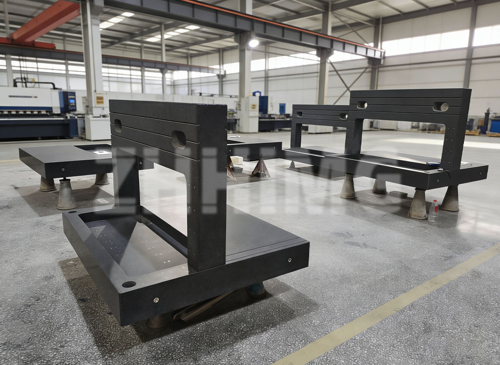
The Role of Granite Foundations in Precision Machining
While this article focuses on machining process factors, the foundation beneath the machine plays a critical role in error control. Granite machine bases provide:
- Vibration Damping: 3-5 times better than cast iron
- Thermal Stability: Low thermal expansion coefficient (5.5×10⁻⁶/°C)
- Dimensional Stability: Zero internal stress from natural aging
- Rigidity: High stiffness minimizes machine deflection
For precision machining applications, especially in aerospace and high-precision manufacturing, investing in quality granite foundations can significantly reduce overall system errors and improve machining accuracy.
Conclusion: Precision is a System, Not a Single Factor
Achieving and maintaining precision machining accuracy requires a comprehensive, systematic approach that addresses all eight key factors:
- Material Selection: Choose materials with appropriate machining characteristics
- Heat Treatment: Manage internal stresses to prevent post-machining distortion
- Tool Selection: Optimize tool materials, geometries, and life management
- Fixturing: Minimize clamping-induced distortion and positioning errors
- Cutting Parameters: Balance productivity with accuracy requirements
- Toolpath Programming: Use advanced strategies to minimize geometric errors
- Thermal Management: Control thermal effects that cause dimensional changes
- Process Monitoring: Implement continuous monitoring and quality control
No single factor can compensate for deficiencies in others. True precision comes from addressing all factors systematically, measuring results, and continuously improving processes. Manufacturers who master this integrated approach can consistently achieve the tight tolerances demanded by aerospace, medical, and high-precision machining applications.
The journey to precision machining excellence never ends. As tolerances tighten and customer expectations increase, the continuous improvement of error control strategies becomes a competitive advantage. By understanding and systematically addressing these eight critical factors, manufacturers can reduce scrap rates, improve quality, and deliver components that meet the most demanding specifications.
About ZHHIMG®
ZHHIMG® is a leading global manufacturer of precision granite components and engineered solutions for CNC equipment, metrology, and advanced manufacturing industries. Our precision granite bases, surface plates, and metrology equipment provide the stable foundation essential for achieving sub-micron machining accuracy. With over 20 international patents and full ISO/CE certifications, we deliver uncompromising quality and precision to customers worldwide.
Our mission is simple: ”The precision business can never be too demanding.”
For technical consultation on precision machining foundations, thermal management solutions, or metrology equipment, contact the ZHHIMG® technical team today.
Post time: Mar-26-2026