
A customer drawing is the starting point for a precision component—not the complete manufacturing instruction.
In ultra-precision manufacturing, a 2D drawing or 3D model may define dimensions, materials, tolerances, surface finish, and geometric controls. It may not reveal the functional importance of a datum, the assembly sequence, the load on an insert, the measurement method, or the environmental conditions in which the part will operate.
That missing context is where many supply problems begin.
A custom precision components manufacturer must do more than machine to nominal dimensions. The work requires structured drawing review, material selection, process planning, controlled production, verified measurement, documented traceability, and protective delivery. This is particularly important for precision granite, ceramic, metal, mineral casting, glass, UHPC, carbon-fiber, and hybrid structures used in metrology, semiconductor equipment, laser systems, CMMs, automation, and precision machine tools.
The most reliable path from customer drawing to finished ultra-precision part begins before any material is cut.
Drawing Review Defines the Project
A productive manufacturing review starts with the latest released drawing revision. The supplier should confirm the part number, material, quantity, dimensional units, tolerances, geometric dimensioning and tolerancing (GD&T), surface requirements, standards, and revision status before preparing the quotation or production plan.
Critical questions should be resolved early:
- Which faces, holes, bores, or interfaces are functional datums?
- Which tolerances are essential to machine performance?
- Does the drawing specify flatness, parallelism, perpendicularity, straightness, position, runout, or profile requirements?
- Are the tolerances realistic for the selected material and component size?
- Which features require 100% inspection?
- Does the part need threaded inserts, bonded interfaces, air passages, cable channels, precision holes, or special mounting surfaces?
- What inspection report, calibration record, or material certificate is required?
GD&T is especially important in precision assemblies because dimensions alone cannot fully define the relationship between features. It communicates requirements for form, orientation, location, and runout so that the manufacturer and customer can work from the same functional intent.
A drawing may call for a very tight positional tolerance on every hole, for example, even though only two locating holes establish the actual assembly datum. Identifying this distinction during design-for-manufacturing review can prevent unnecessary cost and lead-time without weakening the finished product.
Material Selection Is an Engineering Decision
The right material depends on the component’s role in the machine or measuring system.
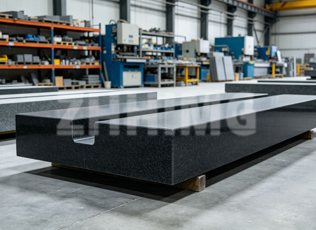
Precision granite components are often selected for large stable bases, bridge structures, surface plates, guideway supports, air-bearing elements, square boxes, and inspection fixtures. Granite can provide stable precision surfaces, vibration damping, corrosion resistance, and non-magnetic behavior.
Precision ceramics may be suitable for electrically insulating, wear-resistant, heat-resistant, or chemically stable components. Metal parts remain important for high-strength interfaces, compact mechanisms, shafts, housings, brackets, and complex machined geometries. Mineral casting and UHPC can support large integrated machine structures where vibration damping, embedded features, and thermal stability are required. Precision glass and carbon-fiber structures may be considered for optical, lightweight, or low-expansion applications.
The material should not be selected only because it is familiar or low cost. It must match operating temperature, load path, vibration level, electrical conditions, chemical exposure, cleanliness requirements, dimensional tolerance, and service life.
At ZHHIMG®, the ability to work with precision granite, ceramic, metal, mineral casting, glass, UHPC, carbon fiber, and precision 3D printing helps customers evaluate the structure as a complete engineering problem. A granite base may need metal inserts. A mineral-cast frame may require precision granite reference rails. A ceramic part may be used inside a larger metal or granite assembly.
Process Planning Protects Precision
Ultra-precision parts cannot be produced successfully through a generic machining route.
A process plan should determine the order of operations, datum transfer strategy, fixturing approach, machining allowance, heat-treatment or curing requirements, stabilization time, final finishing method, and inspection sequence. For large granite components, this may include cutting, rough machining, insert installation, controlled grinding, lapping, assembly, and final geometry verification. For metal components, it may involve rough machining, stress relief, finish machining, grinding, coating, and dimensional inspection. Ceramic components often require diamond grinding, lapping, polishing, or specialized machining methods after sintering.
The sequence matters. Machining a precision rail seat before the component has stabilized can create later alignment issues. Installing threaded inserts after final inspection can affect a critical face if not properly controlled. Finishing a part before all stress-inducing operations are complete can waste time and material.
Design-for-manufacturing review helps identify such risks before production. Industry guidance for tight-tolerance manufacturing emphasizes early tolerance analysis, tool access review, material selection, inspection planning, and realistic process capability.
Inspection Must Match Function
Inspection is not simply a final pass-or-fail activity. It should be planned around the characteristics that determine whether the component will function in the customer’s assembly.
Dimensional inspection can include length, width, height, diameter, hole position, flatness, parallelism, perpendicularity, straightness, runout, surface condition, and assembly fit. Typical measuring equipment may include calibrated calipers, micrometers, dial indicators, electronic levels, roughness testers, CMMs, laser interferometers, optical systems, and dedicated fixtures.
A critical precision component often requires an inspection drawing or ballooned drawing. Each controlled feature receives a reference number connected to a reportable measured value. This creates a clear link between the customer drawing, inspection plan, measurement result, and final documentation.
Dimensional inspection is intended to verify that a component meets the defined drawing or CAD-model requirements, while recorded inspection data supports traceability and compliance with customer or industry standards.
For ultra-precision projects, measurement conditions are also important. Temperature, support method, component cleanliness, probe strategy, instrument calibration, and operator handling can affect the result. A large granite base may require different support points during inspection than a small metal bracket. A thin ceramic component may require low-contact-force measurement to avoid damage.
Documentation Builds Confidence
The finished part should be delivered with the documentation needed for its application. Depending on the project, this may include:
- Dimensional inspection report
- Calibration certificate
- Material certificate or material traceability record
- First article inspection report
- Surface-finish record
- Assembly or insert-location report
- Packing list and product identification
- Photographs before shipment
- Revision-controlled drawing reference
For precision manufacturing, traceability is not paperwork added at the end of production. It is the connection between the ordered drawing, material batch, machining route, inspection result, and delivered component.
Industry practice for high-precision custom parts commonly includes drawing review, DFM support, verified material sourcing, CMM or optical inspection, and documented quality records.
From RFQ to Finished Part
A strong RFQ package helps the manufacturer respond accurately. Include the latest 2D and 3D drawings, material requirements, quantity, critical tolerances, inspection needs, application details, target delivery date, and destination country.
A reliable custom precision components manufacturer will use that information to clarify requirements before production, not after a nonconforming part has been completed. The goal is straightforward: deliver an ultra-precision component that fits the assembly, performs as intended, and arrives with evidence of conformance.
For ZHHIMG®, this process connects custom material selection, precision manufacturing, metrology inspection, assembly capability, and export-ready packaging. The result is not simply a part made to drawing. It is a controlled precision component prepared for the realities of the customer’s machine, laboratory, or production environment.
Post time: Aug-14-2026