
Half of the accuracy ceiling of a granite moving gantry comes from the grinding quality of the stone substrate itself, while the other half is determined by the guide rail installation process. Many projects pass all indicators during factory inspection of granite components, yet suffer from repeated positioning deviation, running jitter and rapid accuracy degradation after machine assembly. The root cause usually lies not in the gantry base material, but in inadequate control of details during guide rail installation. Granite has distinctly different physical properties from metal bases. Simply copying the guide rail installation methods designed for steel frames will easily trigger hidden risks in long-term operation.
First of all, pre-treatment of the granite reference surface is essential. The ground surface cannot be directly used to fasten guide rails. Although granite is ultra-precision ground to high flatness, fine dust, oil stains and tiny invisible dents from minor collision may remain on the surface after handling and transit. Once these micro impurities are trapped under the guide rail base, tightening bolts will induce local deformation of the rail and destroy its straightness. Ordinary rags are insufficient for cleaning; non-woven wiping materials and dedicated cleaning agents are required. After cleaning, high-precision measuring tools shall be used to recheck flatness and roughness of the mounting area. One common misconception should be avoided: do not forcibly grind the granite base locally to fit the guide rail. Excessive partial grinding will break the original internal stress balance of the stone, and the reference surface of the gantry will deform slowly with changes in ambient temperature and humidity.
Next is bolt tightening strategy and stress control, which is the most error-prone part in granite guide rail installation. Granite is far more brittle than steel. Excessive bolt torque will easily cause chipping around bolt holes. Tiny cracks are hard to detect at the initial stage and will expand gradually under alternating vibration during long reciprocating movement of the equipment, eventually leading to loose guide rails. Insufficient tightening force will result in poor contact between rail and base. The guide rail may creep slightly during high-speed movement, causing continuous drift of dynamic accuracy. Instead of fully tightening all bolts at once, installers should adopt diagonal multi-stage fastening. Torque is applied step by step in multiple rounds, and guide rail straightness is remeasured after each round of tightening. Gasket selection must match granite characteristics. Rigid uniform thin gaskets are preferred. Stacking multiple gaskets is forbidden, as stacked gaskets will creep under alternating stress from continuous gantry movement and shift the reference position of guide rails.
For guide rail alignment, static leveling and dynamic pre-evaluation should both be performed. Static inspection alone cannot guarantee long-term performance. Most installers only calibrate rail straightness and parallelness under static conditions, ignoring deformation caused by self-weight loading of the large-span granite gantry. When the sliding carriage moves to different positions, force distribution on the frame changes. During calibration, real working load shall be simulated, and rail parallelness shall be tested at multiple travel positions of the carriage. Otherwise, qualified readings under no-load condition will turn out of tolerance after loading. A single measuring instrument may lead to measurement error. Electronic levels and laser interferometers can be used together to collect continuous data along the full rail length and capture minor local bending.
Ambient conditions affect the whole installation process, and assembly work must be completed in a stable constant-temperature environment. Granite has low thermal conductivity and deforms slightly with temperature variation. If temperature fluctuates in the installation workshop, expansion and contraction of the gantry reference surface will distort rail alignment data. Installation should not be carried out near workshop doors or air vents, as direct airflow causes uneven local temperature of the stone. Floor vibration also distorts readings. If heavy machine tools nearby are running, ground vibration will make measurement values fluctuate and fail to deliver authentic calibration data. Guide rail assembly and calibration are better finished in a shock-resistant constant-temperature clean space. Measurement and bolt locking can only start after the temperature of granite is fully balanced with ambient temperature. 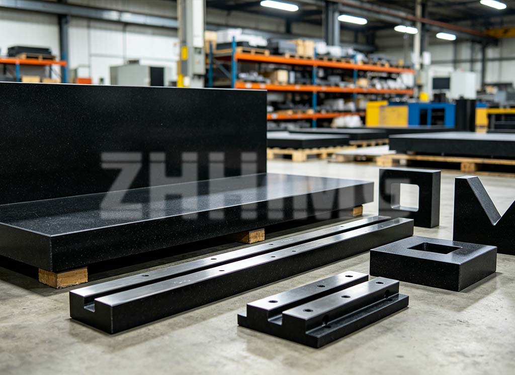
Bonding and transition treatment between guide rails and granite substrate must match the material properties of stone. Some installation plans adopt full rigid adhesive layers. Adhesive shrinks during curing and generates shrinkage stress, pulling the granite surface and altering the shape of reference planes. If structural adhesive is used for auxiliary fixing, low-shrinkage and low-stress special structural glue should be adopted. The coating thickness and area need to be controlled to avoid large-area continuous bonding. Sufficient space for stress release should be reserved. The thermal expansion coefficients of granite and metal guide rails differ. If fully rigidly locked, thermal stress will be generated with temperature change, bending the guide rail or cracking granite bolt holes. Minor thermal compensation space shall be reserved in the design phase to offset stress induced by inconsistent expansion of two materials.
After guide rail installation, full-load machine testing cannot start immediately. Phased running-in verification is required. After all bolts are fastened and calibration finished, the carriage runs slowly across the full travel without full load. Operators observe movement for abnormal noise or jamming, and continuously monitor changes of rail straightness and parallelness. After a period of low-speed running-in, all parameters are rechecked. Only when no drift is confirmed can operating speed and load be raised step by step. This procedure helps expose hidden stress issues in advance and prevents sudden accuracy failure under high-speed conditions after equipment delivery. Skipping running-in and recheck often leads to parameter drift after commissioning. On-site repair and reinstallation of large granite components are extremely costly.
Post time: Sep-20-2026