
A custom precision granite component should never be specified only by length, width, and height.
For a simple granite block, overall dimensions may be enough. For a granite machine base, guideway support, bridge beam, column, air-bearing structure, metrology fixture, or semiconductor-equipment assembly, the important details are usually hidden in the interfaces. Rail-seat geometry, datum relationships, threaded insert locations, support points, mounting surfaces, and inspection methods often determine whether the component performs correctly after installation.
The best custom granite drawing communicates functional intent. It tells the manufacturer which faces establish the reference system, which tolerances are critical, where components will be mounted, how the structure will be supported, and what evidence is needed to confirm compliance.
This article explains the practical information engineering purchasers, quality managers, and lab technicians should include when specifying a custom precision granite component.
Start With the Function
The first step is to define what the granite component will do inside the machine or measurement system.
Will it support linear guide rails? Carry an air-bearing stage? Establish a vertical optical reference? Serve as a CMM base, semiconductor inspection platform, laser-machine beam, or custom measuring fixture? The answer affects material size, geometry, working surfaces, insert design, tolerances, and inspection requirements.
A granite machine base used beneath a linear-motion stage needs controlled rail-seat flatness, straightness, and parallelism. A granite bridge beam may require controlled perpendicularity between its mounting faces and the base datum. A granite surface plate may require certified overall flatness. A granite square box may need accurate angular relationships between several faces.
The drawing should identify:
- The component’s intended application
- Installed equipment and moving loads
- Critical mounting faces and reference datums
- Environmental conditions, including temperature and cleanliness
- Expected operating orientation
- Required service life and maintenance conditions
- Any customer-specific standards or acceptance criteria
Natural granite is commonly used in precision machinery because it provides stable geometry, useful damping, low thermal conductivity, corrosion resistance, and non-magnetic behavior. Its actual performance still depends on the component design and the quality of its installed interfaces.
Define Dimensions and Datums Clearly
A complete granite component drawing should include overall length, width, height, wall thickness where relevant, holes, slots, pockets, recesses, channels, cut-outs, and edge treatments.
More importantly, it should establish a clear datum scheme.
For example, a large granite base may use its primary top surface as Datum A. A long side face may become Datum B, and an end face may become Datum C. Rail mounting planes, insert patterns, locating holes, linear motor pockets, and sensor interfaces can then be dimensioned from these controlled references.
Without a datum structure, every feature may appear dimensionally correct while the assembled machine still suffers from alignment error. A pair of rail seats may be the correct distance apart when measured from outside edges, but their functional parallelism may be outside the machine requirement. A hole pattern may be located correctly relative to a non-critical side face but misaligned relative to the guideway reference.
Use GD&T or an equivalent geometric-control method where appropriate. Flatness, straightness, parallelism, perpendicularity, position, profile, and runout requirements should be assigned only to features that influence the final function.
Typical custom granite component capabilities may include flatness, parallelism, and straightness in the micron-per-meter range, with squareness and insert positioning determined by the part size, geometry, inspection method, and agreed tolerance. These values should be confirmed by the manufacturer for each drawing rather than copied as universal specifications.
Specify Tolerances by Function
Not every feature needs the same tolerance.
Over-tolerancing increases cost, lead time, inspection effort, and manufacturing risk. Under-tolerancing can create assembly problems or unstable machine behavior. A useful drawing separates critical features from non-critical features.
Typical requirements may include:
| Feature | Typical specification focus |
|---|---|
| Primary measuring surface | Overall flatness and surface condition |
| Guideway mounting face | Flatness, straightness and local contact condition |
| Parallel rail seats | Parallelism, height difference and straightness |
| Vertical reference face | Perpendicularity to the primary datum |
| Mounted component holes | True position relative to functional datums |
| Granite bridge interfaces | Parallelism, squareness and assembly fit |
| Air-bearing surfaces | Flatness, local geometry and surface finish |
| Non-functional exterior faces | General dimensional tolerance only |
The tolerance must be realistic for the component size. A 300 mm granite fixture can be controlled differently from a 6,000 mm granite machine base. Long structures also require correct support during machining and inspection so that self-weight does not create measurement error.
For measuring plates, DIN 876 Grade 00, Grade 0, and Grade 1 are commonly used to define overall flatness suitability for laboratory, inspection, and workshop applications. Grade selection should not automatically be applied to every custom granite machine component, because rail interfaces, insert locations, and assembly datums may need their own separate tolerances.
Design Threaded Inserts and Interfaces Early
Threaded inserts allow granite components to support rails, motors, fixtures, optical brackets, air bearings, scales, sensors, cable supports, and other machine elements. They should be included in the initial design, not added after final surface processing.
A complete insert specification should identify:
- Insert material, such as stainless steel or another required alloy
- Thread standard, including metric or imperial thread type
- Thread size and effective thread depth
- Insert outer diameter and installation depth
- Hole location and positional tolerance
- Distance from edges, corners, and nearby inserts
- Bolt preload, pull-out load, shear load, and service condition
- Whether locating pins, reamed holes, keyways, or shoulders are required
- Any cleanroom, corrosion-resistance, or vacuum-compatibility requirement
Threaded inserts, bushings, T-slots, and precision locating features can be integrated into granite components to create reliable interfaces for guiding, clamping, and assembly. High-strength bonding systems are commonly used to secure these inserts.
The key point is that inserts should not carry all positional responsibility. Where precise repeatable assembly is required, use a combination of threaded fasteners for clamping and dowel holes, shoulders, keys, or other locating features for position control.
Plan Inspection Before Manufacturing
The inspection plan should be discussed during quotation and drawing review.
A customer may require a dimensional report, first-article inspection report, calibration certificate, material declaration, or a dedicated report for critical rail seats and insert locations. These requirements affect the manufacturing route, inspection time, support arrangement, measurement equipment, and final cost.
For a custom precision granite component, inspection may include:
- Overall dimensions
- Flatness of primary working surfaces
- Straightness of rail mounting faces
- Parallelism between rail seats or opposite faces
- Perpendicularity between base, side, and end datums
- Position, thread quality, and depth of inserts
- Hole diameter, reamed-hole geometry, and dowel-hole position
- Surface roughness where specified
- Assembly fit with customer-supplied components
- Visual condition, edge finish, and packing condition
High-precision granite machining and lapping can achieve micron-level geometry, but the reported result is only meaningful when the measuring method, support condition, temperature, measurement instrument, and acceptance criterion are defined. Precision granite suppliers commonly use sensitive electronic levels, autocollimators, indicators, roughness testers, and reference standards for geometry verification.
Include Handling and Installation Requirements
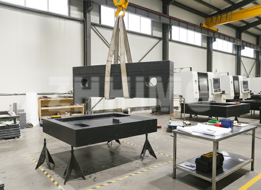
Granite is strong in compression but can be damaged by impact, inappropriate lifting, or concentrated loading at unsupported edges. Large components should include lifting features, approved lifting locations, weight information, center-of-gravity guidance, support-point information, and packaging requirements.
Specify whether the component will be shipped as a loose granite part, a bonded granite assembly, or a pre-assembled structure with inserts, guideways, motors, or fixtures. The supplier should also know the destination country, required export packing, delivery location, unloading capability, and available installation equipment.
At ZHHIMG®, custom precision granite components can be designed as individual machine bases, guideway supports, bridges, columns, air-bearing elements, metrology fixtures, or larger integrated assemblies. Drawing review normally includes material selection, critical datum surfaces, insert arrangement, inspection requirements, handling method, and final assembly needs.
A Better RFQ Produces a Better Component
For an accurate quotation, provide the latest PDF drawing and 3D model, required quantity, material preference, application details, critical tolerances, insert information, required standards, inspection documents, packaging requirements, destination country, and target delivery date.
A well-specified custom precision granite component reduces clarification delays, prevents tolerance misunderstandings, and improves the chance of first-time assembly success. The strongest specification is not the one with the most tolerances. It is the one that clearly identifies the dimensions, interfaces, and inspection controls that actually matter to machine performance.
Post time: Aug-17-2026