
A large granite machine frame is not calibrated in the same way as a standard granite surface plate. Its geometry may include multiple precision planes, rail-mounting faces, threaded inserts, bores, shoulders, slots, air-bearing surfaces, and metal interfaces. The inspection task is therefore not limited to “checking flatness.” It is a controlled verification of the functional relationships defined in the engineering drawing.
For global engineering purchasers, quality managers, and laboratory technicians, the calibration process should begin before the first instrument is placed on the granite. The component must be stable, correctly supported, clean, thermally settled, and inspected against a clear acceptance plan.
At ZHHIMG®, large precision granite workpieces are handled as structural metrology components. The inspection method is selected according to the part’s function, size, tolerance requirements, and agreed reference datums. This approach is especially important for granite frames used in CMM systems, semiconductor equipment, laser platforms, optical inspection machines, precision automation, and large machine-base assemblies.
1. Review the Drawing and Define Datums
The first step is document review. The inspection team should identify the primary datum surface, secondary and tertiary datums, critical dimensions, functional mounting faces, insert locations, and required geometric tolerances.
Typical requirements for a granite machine frame calibration may include:
- Flatness of the main granite reference surface
- Straightness of rail-mounting faces
- Parallelism between two guideway-support planes
- Perpendicularity between vertical and horizontal reference faces
- Position of threaded inserts, dowel holes, or assembly bores
- Height relationship between multiple mounting pads
- Alignment of air-bearing or motion-system interfaces
- Surface roughness or finish requirement for designated areas
A common inspection mistake is measuring every visible granite surface with equal priority. In reality, not every face controls machine accuracy. The inspection plan should concentrate on the surfaces and dimensions that affect the installed motion system, optical path, measurement axis, or assembly relationship.
The purchaser and supplier should agree on the drawing revision, tolerance system, measurement units, acceptance standard, and report format before final inspection begins.
2. Stabilize the Granite and Environment
Granite is valued for dimensional stability, but it is not immune to temperature gradients. A large machine frame moved from a warm machining area into a controlled inspection room needs time to stabilize. Direct sunlight, localized airflow, nearby doors, handling equipment, and warm metal fixtures can all affect short-term measurement results.
The workpiece should be placed in a stable inspection environment and allowed to reach suitable thermal equilibrium. Temperature at several locations may be recorded, particularly for large or thick structures. The surface must be clean, dry, and free from dust, oil, packaging residue, metal chips, or abrasive particles.
Inspection service guidance for granite reference surfaces commonly includes confirming that the component has reached the required ambient condition, cleaning the surface, checking for wear or damage, and recording thermal conditions before flatness testing.precisionsolutionsinc+1
For a large granite frame, temperature information should become part of the final report when the tolerance is tight or the component will operate in a controlled metrology environment.
3. Establish Correct Support Conditions
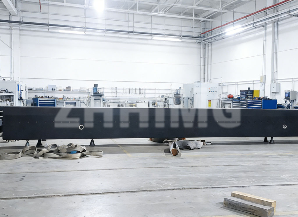
Support arrangement directly affects measured geometry. A granite component should be supported at the points specified in the approved drawing or engineering support plan. Incorrect support can introduce bending, local stress, or an apparent flatness error that does not represent the part’s intended working condition.
Three-point support is commonly used for granite reference plates because it avoids over-constraint. Larger machine frames may require more support points due to their size, mass, geometry, and installed equipment loads. In those cases, each support must be adjusted carefully so the structure is neither rocking nor forced into distortion.
The inspection team should verify:
- Support-point position
- Level of each bracket or isolator
- Contact condition at all specified supports
- Absence of unintended contact with the floor or fixture
- Stability during movement of the measuring instrument
- Alignment with the component’s final installation orientation
ASME B89.3.7 provides established surface-plate calibration guidance and stresses correct support conditions for granite reference surfaces. For a complex machine frame, however, the customer drawing and agreed inspection plan remain the primary acceptance documents.
4. Select the Right Measurement Method
No single instrument is suitable for every granite workpiece. The method depends on the surface size, tolerance, accessibility, required uncertainty, and the geometric characteristic being checked.
Common tools include:
| Inspection target | Typical instruments |
|---|---|
| Large-area flatness | Electronic level, autocollimator, laser interferometer |
| Long straightness | Laser system, precision straightedge, electronic level |
| Parallelism | Electronic level, dial indicator, laser alignment system |
| Perpendicularity | Granite square, autocollimator, CMM, precision indicator setup |
| Insert or bore position | CMM, laser tracker, coordinate measurement system |
| Local surface variation | Repeat-reading gauge or indicator-based fixture |
| Surface condition | Visual check, roughness tester where specified |
For large granite surfaces, electronic levels, autocollimators, laser interferometers, and calibrated straightedge-indicator methods are recognized approaches for evaluating overall flatness. The measurement data is typically collected along planned lines and combined to calculate deviation from a reference plane.
5. Measure Flatness and Straightness Systematically
The main reference surface should be divided into a measurement grid. Grid spacing is determined by the part size, tolerance, instrument resolution, and agreed method. Longitudinal, transverse, centerline, perimeter, and diagonal paths may all be needed.
The operator records readings in a consistent sequence. Every location must be traceable to the inspection map. If electronic levels or a laser system are used, the software or calculation method should identify the high and low points, total deviation, and reference plane.
Straightness checks on long rail seats or guideway pads should be performed separately from full-surface flatness checks. A machine frame can meet overall flatness while one long functional rail interface exceeds its straightness tolerance. That is why the drawing must define each critical feature independently.
6. Inspect Inserts and Assembly Interfaces
Threaded inserts, locating bores, mounting pads, and metal interfaces often determine how successfully the granite frame integrates into the final machine.
The inspection report should confirm:
- Insert quantity, thread type, and installation condition
- X, Y, and Z position of critical inserts
- Height consistency of mounting pads
- Position of dowel holes and alignment bores
- Perpendicularity or parallelism of mounted faces
- Absence of damage around insert locations
Where inserts support linear guideways or motion components, their positional tolerances should be checked in relation to the designated granite datum—not simply in relation to the nearest edge.
7. Issue a Traceable Final Report
A complete calibration report should include the workpiece identification number, drawing revision, material description, inspection date, environmental condition, instrument identification, calibration status, support arrangement, measurement grid, readings, calculated deviations, tolerance comparison, and inspector approval.
If the component does not meet the required tolerance, the supplier should identify the nonconforming feature clearly. Rework, re-lapping, local correction, or engineering review may then be considered before acceptance.
A well-calibrated granite machine frame becomes a dependable foundation for the equipment built on it. ZHHIMG® supports this process through custom granite manufacturing, large-part inspection, calibrated measuring instruments, and drawing-based quality documentation. For high-value metrology or automation projects, calibration is not the final administrative step. It is the evidence that the granite structure can perform its intended function.
Post time: Aug-11-2026