
When customizing granite bases, beams and substrates, many equipment manufacturers only mark length, width, thickness and hole positions on drawings. They ignore the unique reference system, machining limits and metrology acceptance conditions of granite materials. Incomplete drawing information or ambiguous reference definition can easily lead to misunderstanding during manufacturing, finished geometric tolerance failing to meet assembly requirements of complete machines, or even stress deformation after grooving and drilling, delaying projects. With years of experience in custom ultra-precision granite components, ZHHIMG Group (ZHHIMG®) sorts out key parameters that must be clearly marked on custom drawings, making drawings a unified technical basis for machining, inspection and acceptance.
Definition of reference system is the core to be marked first on the whole drawing. All geometric tolerances of precision granite parts must be bound to clear datums, instead of taking the top surface as the main reference by default. Drawings need to select the main reference surface (usually the main working surface), secondary datum and tertiary datum, mark datum symbols and explain rules for datum establishment. A common mistake made by customers: holes and grooves are marked separately without a unified reference chain, resulting in out-of-control position tolerance of guide rail mounting grooves and positioning pin holes relative to the main working surface. Drawings should also specify acceptance rules of datum surfaces, clarify whether flatness inspection adopts full-area grid method or diagonal method, and agree on temperature for metrology, so as to avoid data disputes caused by inconsistent environmental conditions between factory inspection and customer re-measurement.
Geometric tolerance parameters of main working surface directly determine the benchmark grade of complete equipment. Drawings need to mark flatness, flatness fluctuation and parallelism of the main working surface. Precision grades such as grade 000 and grade 00 are selected according to equipment requirements, and tolerance unit (micron) shall be noted. For long-travel beams and large-size substrates, besides overall flatness, straightness should also be marked to control long-wave ripple errors. When side faces serve as assembly datums, perpendicularity between side faces and main working surface and perpendicularity between adjacent side faces should be marked. These geometric tolerances cannot be simply described by a general precision grade; tolerance values must be bound to specified datums to guarantee coplanarity after assembly of guide rails and optical brackets.
Structural feature dimensions and geometric tolerances of holes and grooves. For every counterbore, pin hole, through hole, wiring groove and weight-reduction cavity on drawings, besides basic dimensions, position tolerance of hole spacing, perpendicularity of hole axis relative to reference surface, straightness of grooves and flatness of groove bottom must be marked. Supplementary details should be added for different types of holes: aperture tolerance for pin holes; counterbore depth and concentricity for counterbore holes; thread specification, insert depth and anti-drop requirements for embedded thread holes. Granite is brittle material. Chamfers or fillets at hole edges should be marked on drawings, and the allowable range of minor chipping must be specified to prevent uneven stress on fasteners during assembly. For air flotation air channels and vacuum suction grooves, flatness of sealing surface and surface quality requirements should be marked.
Material and surface treatment parameters. Drawings need to specify granite material grade, distinguish common stone from low-expansion black granite, and note material indicators such as density and thermal expansion coefficient to avoid misuse of materials. Surface roughness is critical: Ra value marked on main reference working surface and guide rail mounting surface; roughness can be relaxed on non-matching side faces and inner walls of weight-reduction cavities. Meanwhile, surface micro-pore sealing treatment requirements should be marked, stating whether passivation sealing is required and whether paint spraying is forbidden. Notes on drawings shall specify that cracks, pinholes and loose mineral bands in stone matrix are not allowed, and define judgment criteria for appearance defects.
Additional technical parameters of load and working conditions are unique contents of granite drawings different from ordinary metal part drawings. Drawings need to mark static load after component assembly, dynamic load of moving modules and temperature & humidity range during equipment operation. ZHHIMG engineers can conduct mechanical simulation in advance according to load information to evaluate deflection risks brought by hole opening and weight-reduction cavities. Drawings should also mark support point positions and support modes. The support layout of granite bases directly affects self-weight deformation. Missing support point information on many drawings leads to obvious flatness difference when finished parts are placed flat and supported on site by customers.
Metrology acceptance and inspection specifications. In the technical requirement column of drawings, acceptance standards shall be specified, including GB, DIN, ASME, ISO and other specifications. Instrument types and constant-temperature conditions for measurement should be noted. Meanwhile, it is necessary to clarify inspection items to be included in metrology reports delivered together with goods: full-area flatness contour map, hole position data, perpendicularity and parallelism records. Drawings can also mark agreements related to aging processes, such as whether multi-round constant-temperature standing for stress relief during processing is required. This item directly affects long-term precision stability of finished products. 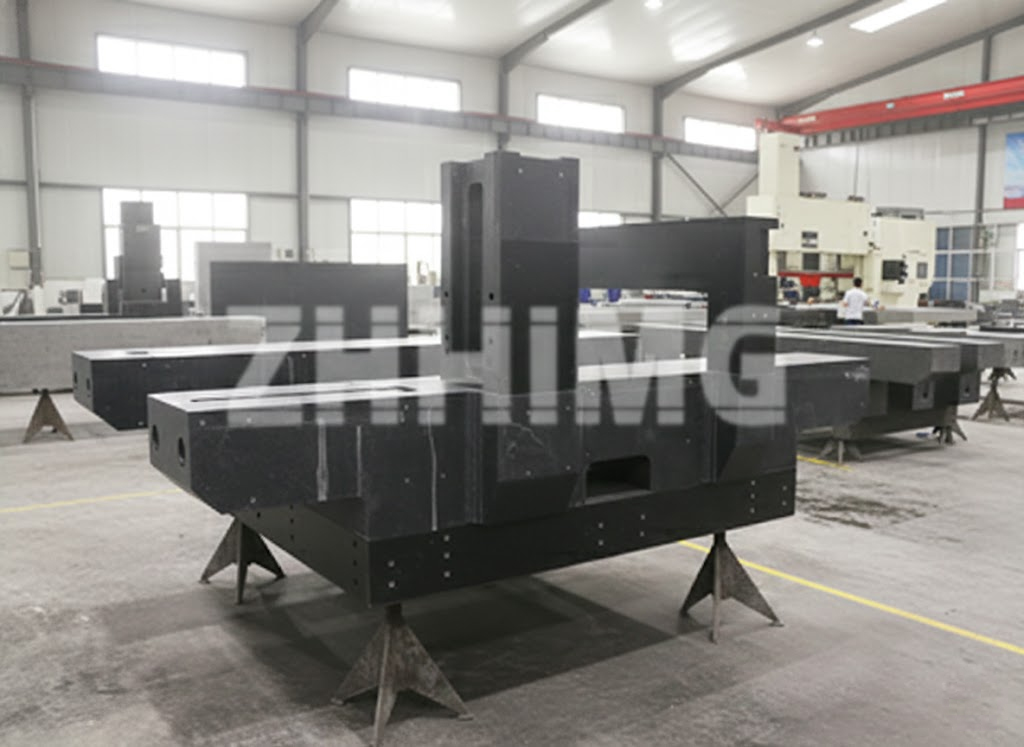
Edge, safety and machining restriction notes. Granite is brittle. Drawings should mark protection requirements for all edges, distinguish reference edges from non-working edges. For local thin walls and large-span hollow structures, structural risks should be prompted in drawing notes, so that the factory can optimize wall thickness at the process stage. Transport protection requirements and hoisting points should also be marked. Hoisting hole positions and load limits of large-size granite beams and bases shall be specified to prevent stone cracking caused by uneven hoisting stress.
In short, drawings for custom precision granite components cannot follow marking habits of ordinary metal parts. A complete drawing needs key information including datum definition, geometric tolerance of working surface, geometric tolerance of hole and groove positions, material and surface parameters, support and load conditions, metrology acceptance standards, edge and machining constraints. ZHHIMG Group can participate in drawing review in advance, check parameter rationality, predict stress and deflection risks brought by hole opening and weight reduction, reduce drawing ambiguity, and ensure finished granite components meet assembly and precision requirements of automation, semiconductor and optical inspection equipment in one pass.
Post time: Oct-13-2026