
A granite air-bearing guideway should be specified as a functional part of a precision motion system, not simply as a granite component with a smooth surface. Its suitability depends on how the guideway geometry, working surfaces, support arrangement and inspection requirements match the selected air bearings and the machine design.
For equipment manufacturers, a clear specification helps connect the mechanical drawing with the intended operating conditions. It also gives the granite manufacturer, air-bearing supplier and system integrator a common basis for reviewing the component before production begins.
This article explains what to discuss when ordering a custom granite air-bearing base, guideway or beam, and how to establish an inspection agreement that reflects its intended function.
Start with the Air-Bearing System and Its Interfaces
The first step is to define what the granite component will do within the assembly. A horizontal guideway supporting a moving carriage has different interfaces from a vertical reference surface or a beam used in a multi-axis arrangement. The drawing should identify which granite surfaces interact with the air bearings, which surfaces support other components and which features serve as assembly references.
It is equally important to define the scope of supply. A granite air-bearing guideway, an air-bearing carriage and a complete motion stage are not interchangeable products. The granite supplier may be responsible for the base and its working surfaces, while another supplier provides the air bearings, motor, encoder and controller. Alternatively, the project may include a broader assembly scope. These responsibilities should be agreed before quotation and documented in the order.
At this stage, provide the proposed bearing arrangement, travel direction, loading information and installation orientation. Where available, include the air-bearing manufacturer’s requirements for the mating surface. Those requirements should guide the technical review rather than a general assumption that every air-bearing application needs the same granite specification.
For a ZHHIMG project inquiry, a drawing of the granite component together with an assembly view provides a useful starting point. If the bearing selection or support arrangement is still under development, identify those items as open questions.
Define Geometry and Surface Finish Separately
The expression “high-precision surface” is not sufficiently specific for manufacturing or acceptance. A functional drawing needs to identify the controlled surface, the required geometric relationship and the region over which each requirement applies.
Flatness describes the form of a surface, while parallelism and perpendicularity describe relationships to specified references. Straightness requirements may also be relevant along a defined direction or measurement line. These controls should not be substituted for one another, and a single tolerance should not be expected to describe every aspect of guideway geometry.
For example, a design may require a horizontal bearing surface and a vertical guiding surface. The drawing should establish the requirements for each surface and their relationship, rather than applying an undefined “overall precision” value to the entire component. If a requirement applies only to the bearing travel region, that region should be clearly identified.
Surface finish also needs its own specification. A surface that appears polished is not automatically suitable for the selected air-bearing arrangement. Visual appearance should not replace an agreed surface-finish requirement or the bearing supplier’s mating-surface criteria.
Where a roughness parameter is specified, state the relevant surface and the agreed evaluation method. Avoid treating one roughness value as a complete description of all surface characteristics. The technical review should also address the treatment of pores, chips, scratches, repaired areas or other local features within the functional bearing path.
The most useful specification is not necessarily the one with the smallest numbers. It is the one that connects each requirement to the bearing design, functional region and agreed inspection method.
Review the Complete Working Surface
The usable guideway area should be marked clearly on the drawing. This is especially important when the granite component contains holes, slots, pockets, inserts or openings near the bearing path.
Do not assume that a feature is acceptable simply because it does not interfere with the nominal outline of the carriage. Its position should be reviewed against the actual bearing footprint and full travel range. Any surface interruption within that region needs agreement with the air-bearing designer.
Edge conditions also deserve attention. Chamfers, edge breaks and transitions should be defined where they are close to the working area. The drawing should distinguish between general edges and edges that affect the functional guideway surface.
If the granite base includes threaded inserts for motors, encoders, brackets or other equipment, specify their positions and mounting requirements. Clarify whether final geometry is inspected before or after the installation of inserts and attached components. Where assembly work is included, the inspection sequence should reflect the agreed delivery condition.
For long granite beams or multi-surface structures, an assembly drawing can be particularly useful. It helps the parties review access, orientation and interfaces that may be difficult to understand from an isolated part drawing.
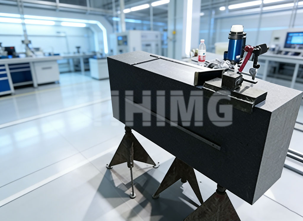
Agree on Support and Inspection Conditions
An inspection result should be read together with the conditions under which it was obtained. For a custom granite air-bearing guideway, the acceptance agreement should describe how the component is supported, oriented and prepared for measurement.
The supplier and buyer should agree on the support locations and whether the component is inspected as an individual part or as an assembly. If the intended installation uses a different support arrangement, that difference should be reviewed before acceptance criteria are finalized.
Environmental conditions should also be addressed. Rather than stating only that inspection takes place in a temperature-controlled room, agree on the conditions to be recorded and any preparation or stabilization procedure required by the project. If the customer’s specification sets particular environmental limits, include them in the inquiry.
The inspection method should be selected according to the feature and tolerance being evaluated. An instrument name alone does not establish that a measurement is suitable. The measurement layout, reference system, data evaluation and relevant measurement capability all belong in the discussion.
For critical working surfaces, request a measurement layout showing where data will be collected. This helps establish whether the inspection covers the functional region identified on the drawing. It also makes the report more useful during receiving inspection and subsequent assembly.
Make the Inspection Report Useful for Acceptance
Inspection documentation should be agreed before manufacturing, not requested for the first time when the component is ready to ship.
A useful report connects the delivered component with the approved drawing revision and the agreed acceptance requirements. It should identify the features inspected, applicable limits and reported results. Where required, it should also describe the datum arrangement, support setup, measurement locations, environmental conditions and equipment used.
For a critical guideway surface, a result map or measurement layout may provide more useful information than a pass/fail statement alone. The required format should be discussed during technical review so that the supplier understands what the customer needs for its own quality records.
Calibration documentation for inspection equipment and an inspection report for the granite component serve different purposes. If the project requires particular calibration references, a measurement uncertainty statement or an independently issued report, state that requirement explicitly.
Acceptance should also remain within the agreed scope. Inspection of the granite guideway does not, by itself, establish the positioning accuracy or dynamic performance of a complete motion stage. Those results require evaluation of the relevant assembled system under its specified test conditions.
Prepare a Clear Inquiry for Your Granite Air-Bearing Guideway
A productive inquiry explains the application as well as the component dimensions. Send the controlled drawing, a matching model if available, the intended bearing arrangement, working travel region, loading information and proposed support conditions. Include the mating-surface requirements supplied by the air-bearing manufacturer and identify any requirements that remain provisional.
State whether you need a granite component only, a component with inserts and hardware, or a more complete assembly. Define the inspection documents expected at delivery and any special requirements for packaging, lifting or receiving inspection.
This information gives both parties a clearer basis for discussing feasibility, quotation and acceptance. It also helps prevent a visually similar component from being treated as functionally equivalent when its interfaces or inspection requirements differ.
At ZHHIMG, we welcome drawing-based inquiries for custom granite air-bearing bases, guideways and beams. Share your application requirements and identify the areas that need joint technical review, so that the proposed supply and inspection scope can be discussed clearly.
Our commitment to customers is simple: no cheating, no concealment and no misleading. For a precision guideway project, that begins with clearly defined requirements, transparent technical communication and an agreed basis for acceptance.
Post time: Nov-17-2026