
What an air bearing actually is
An air bearing is a fluid-film bearing in which the working fluid is compressed air. Instead of balls, rollers or an oil film, a thin layer of pressurised gas — the air film — separates the moving and stationary parts, so the two surfaces never touch during normal operation. Everything that follows, from the near-zero starting friction to the very fine motion resolution, comes from that single fact: the load is carried by gas pressure, and the geometry of the gap is what defines motion quality.
A granite air bearing uses a precision-lapped granite surface as one of the two bearing surfaces. The granite face is the guideway; the carriage carries the bearing pads that ride above it. Granite is chosen for the guideway because it holds flatness over long lengths, has low thermal expansion, and damps vibration — three properties the air film cannot provide by itself.
How the air film forms: orifice, gap and pressure
The diagram below shows the working principle as a cross-section. Compressed air enters through an inlet and passes through a restriction — an orifice or a porous medium — into a shallow recess, and from there escapes through the gap between the pad face and the granite guideway.
Air bearing cross-section: supply, restriction, gap, guideway
Carriage (moving part)
carries the load, drive and encoder
air inlet
compressed air
restriction
orifice / porous
pressurised recess
air film gap — typically a few micrometres to ~10 µm
air escapes outward through the gap
Granite guideway (lapped datum surface)
flatness, surface texture and parallelism of this face set the motion error budget
load is carried by air pressure — no metal-to-metal contact in normal running
The pressure in the recess is higher than ambient; the gas escapes to atmosphere through the gap. Because the restriction chokes the flow, the recess pressure rises when the gap closes and falls when the gap opens. That self-regulating behaviour is what gives the bearing its stiffness: push the carriage down and the film pushes back harder. The size of the restriction and the size of the gap therefore set both the load capacity and the stiffness — they are not incidental details but the primary design variables.
A feature worth noting from the diagram: the escaping air carries heat and any particles away from the bearing region, and for many applications the exhaust is drawn off rather than dumped into the machine. In cleanroom and semiconductor tools this exhaust path is part of the tool design, not an afterthought.
Air bearings versus rolling and sliding guideways
The three guideway families solve the same problem in fundamentally different ways:
- Rolling guideways: steel balls or rollers in a raceway. They are compact, carry heavy loads and are inexpensive, but the rolling elements cause micron-level motion reversal error, they wear, and they need lubrication.
- Sliding guideways: two surfaces in direct contact, sometimes with an oil film. They combine high stiffness with high damping, but they exhibit stick-slip at low speeds and require lubrication and wear management.
- Air bearings: a pressurised gas film with no contact. Starting friction is very low, no lubrication is needed, and motion is smooth down to very small increments. In exchange, they require a clean and pressure-regulated air supply, offer lower load capacity for the same envelope, and are less tolerant of surface damage.
The practical consequence is that air bearings are chosen where motion quality dominates — metrology stages, precision scanning, wafer handling and inspection — and rolling guides are chosen where load, cost and robustness dominate. A granite air-bearing stage is therefore a system decision, not a component substitution.
What the granite guideway has to deliver
The air film is only as good as the surface it runs on. Four surface properties matter:
- Flatness: the film thickness is only a few micrometres, so long-wavelength flatness error directly modulates the gap and therefore the position of the carriage along its travel.
- Surface quality: the lapped texture must be consistent — scratch-free and free of local steps. A local bump changes local pressure and shows up as a pitch or yaw disturbance.
- Parallelism: where two guideways carry one carriage, their relative parallelism across the travel sets the preload balance between opposing pads. Misalignment loads one side and unloads the other.
- Film stability: the gap must remain stable over the whole travel, which is a joint outcome of flatness, supply pressure stability and the stiffness of the carriage structure itself.
This is why a granite air bearing guideway is usually supplied as a matched pair of lapped granite surfaces plus the carriage, rather than as separate items to be assembled on site.
Design parameters that decide performance
When specifying an air-bearing system, these are the variables that determine whether the result meets the application:
- Preload: whether the carriage is preloaded by an opposing pad, by vacuum, or by the weight of the moving mass. Preload sets the effective stiffness and determines whether the bearing can take moments and reversing loads.
- Air supply cleanliness: because the gap is a few micrometres, the filtration grade must match the gap. Oil, water and particles in the line will block restrictions or scratch the granite face.
- Pressure stability: recess pressure follows supply pressure, so regulator stability and any pressure ripple from the compressor appear directly in the film thickness and thus in positioning repeatability.
- Load and stiffness: total load (static plus dynamic) and the required stiffness at the point of interest. Stiffness is a function of pad area, gap and supply pressure, and should be quoted at a stated gap and pressure — not as a single number.
- Motion error budget: straightness, pitch, yaw and roll of the carriage over its travel. These follow from guideway flatness and parallelism, and they should be specified per axis rather than as an overall figure.
For all of these, the right numbers come from the supplier’s test data and the specific design — a bearing pad does not have one load capacity or one stiffness in isolation.
What a granite air-bearing assembly looks like
The photo below shows a long granite beam with a bearing carriage mounted on top, standing on support stands in our workshop. The granite has been lapped on the working faces, the carriage carries its own air connections, and the whole piece is handled as a matched assembly — the beam and its carriage are inspected together because the motion quality is a property of the pair.
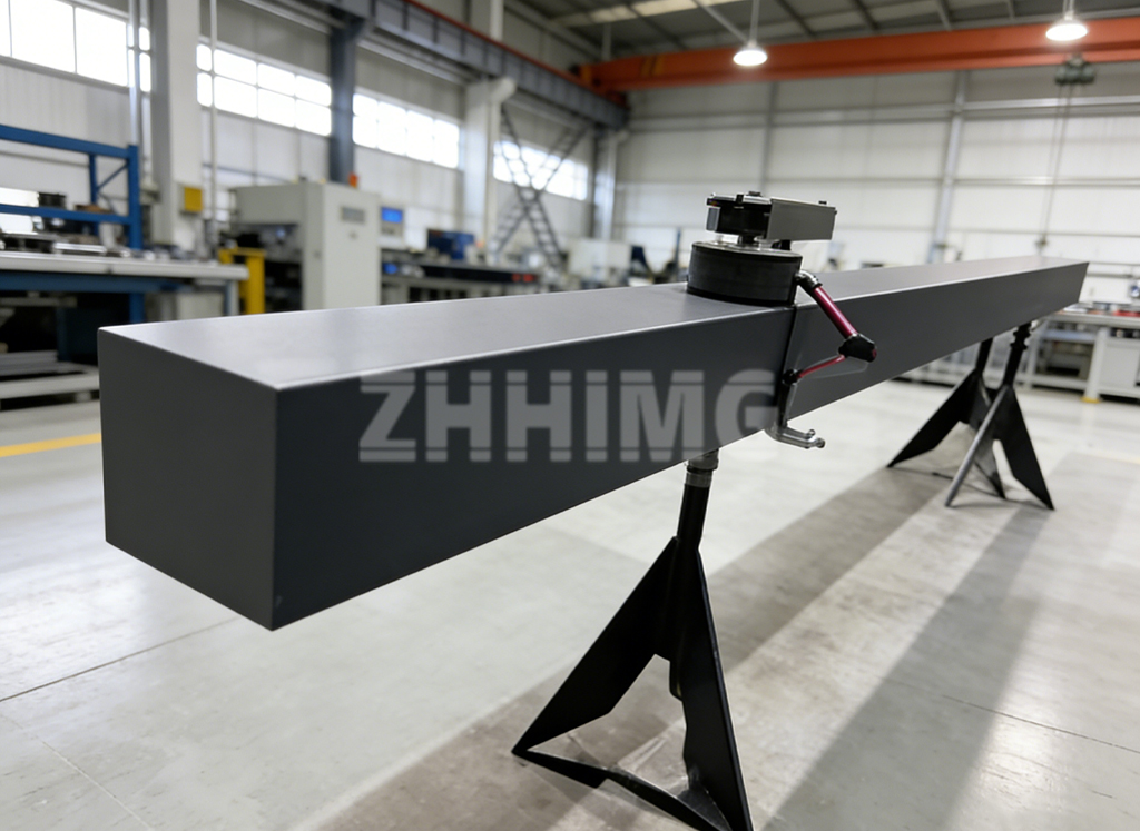
Pieces like this are typical of the custom work we do on granite air bearing guideways: the granite beam length, the pad positions, the preload arrangement and the air plumbing all follow the customer’s motion requirement rather than a catalogue entry.
Information needed for a design review
To turn an air-bearing concept into a manufacturable design, we need the motion envelope and travel length, the moving mass and any process loads, the required stiffness and where it is measured, the straightness and angular error budget per axis, the air supply pressure available and its filtration, and the intended environment. With those, a granite air bearing manufacturer can propose a guideway geometry, pad arrangement and preload scheme, and state the expected performance at specified conditions.
Send your stage layout, load and stiffness requirements, air supply conditions and error budget to ZHHIMG, and you will receive a design review and a quotation for the guideway and carriage assembly.
Post time: Oct-13-2026