
Granite Bases for Air-Bearing Stages: A Buyer’s Specification Checklist
An air-bearing stage is only as good as the granite it rides on — but buying that granite is not the same as buying the stage. Many teams working on a granite air bearing stage discover late in the project that nobody defined who supplies what: who machines the air-bearing surfaces, who holds the interface tolerances, who verifies the assembly, and who is responsible when the stage does not fly. This article is a specification checklist for engineers procuring granite bases, air-bearing guideways, or complete assemblies — it defines the scope decisions to make before the RFQ, the data to provide, and the inspections to agree on in advance.
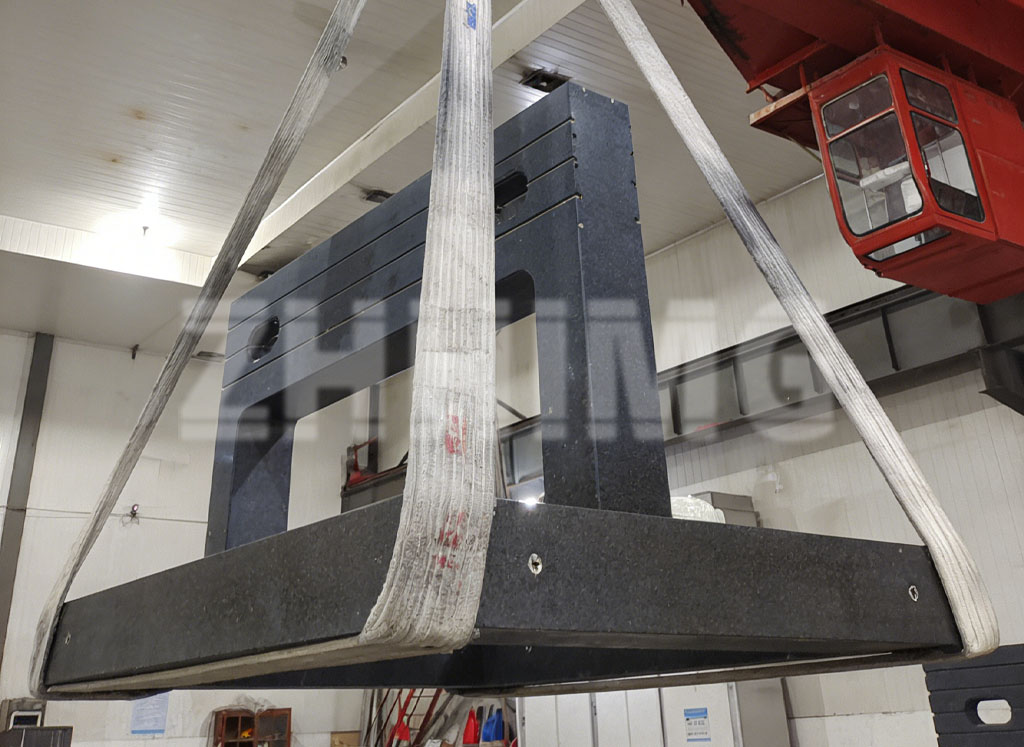
1. Define the delivery scope before anything else
The single most important line in your enquiry is the scope statement. These are different purchases with different prices, lead times and verification duties:
A granite base only: the stone machined to your drawing, including ground or lapped faces, inserts and pockets — you integrate the air bearings yourself.
A granite base with machined air-bearing surfaces: the stone plus lapped guideway surfaces defined to the flatness and finish the air-bearing supplier requires. Here the critical data is the bearing maker’s surface specification — gap, flatness, roughness, porosity limits — which must appear on the drawing, not in an email.
A functional assembly: granite plus bearings plus preload hardware, verified moving or at least verified static. ZHHIMG offers this level as an integrated machine bed and air-bearing assembly; the verification duties for a functional assembly are strictly larger and must be priced as such.
State the scope explicitly, including who supplies the air bearings, who installs them, and who owns the interface tolerances between stone and bearing pads.
2. Load, travel, installation and environment data
The granite geometry is derived from your machine’s physics, so provide:
Payload and mass distribution: static mass, moving mass, centre-of-gravity travel, and dynamic loads from acceleration or braking if the base carries linear motors. Point loads from bearing pads matter more than totals — give pad positions and loads where possible.
Travel and envelope: axis travel range, the stroke of each carriage, and the space reserved for cables, brakes, encoders and end stops. A base sized without cable-drag-chain space will be re-cut later at everyone’s expense.
Installation: how the granite is supported (three-point kinematic or defined multi-point), levelling mechanism, and what it stands on. For air-bearing stages, the support structure’s stiffness and isolation directly affect the performance your bearings can deliver.
Environment: temperature range and stability, vibration environment (floor spectra if known), cleanroom class if applicable, and humidity. These decide material finish choices, material stability measures, and how performance should be verified at the end.
3. Drawing requirements: mark the functional surfaces
An air-bearing base drawing fails in a predictable way: everything is toleranced equally, so nothing is prioritised. Instead, classify and mark every face:
Air-bearing surfaces: the guiding faces the pads run on. These carry the tightest flatness and surface-finish requirements and usually a joint requirement across separate faces (coplanarity between upper and lower guide rails, perpendicularity between axes). Tolerance them as a system, not per-face in isolation.
Reference datums: which faces the machine builder will align to, and their priority order. Every other tolerance should reference these datums.
Mechanical interfaces: rail-seat or pad-mounting faces, insert positions with true-position tolerances, and preload surfaces where bearings are clamped against. Note which faces are lapped, which ground, and which are machined-only.
Non-functional areas: pockets, cable channels, covers. State explicitly that general tolerances apply — over-tolerancing unused faces is a common cost driver.
If your air-bearing supplier has a “granite interface drawing”, attach it to the RFQ rather than re-drawing their requirements — transcription errors at this interface are a classic failure source.
4. Coordinating the interfaces between granite, bearings and motion
Three interfaces decide the project’s success, and each needs an owner:
Stone to bearing pad: surface finish and flatness at the pad running faces, insert torque limits, and who measures these features and how. The finished air-bearing granite surface, not the drawing intent, determines the air gap behaviour.
Stone to machine frame: datums, locating scheme, and thermal decoupling if the machine around the granite expands differently than the stone.
Granite to motion system: positions of motor mounts and encoder references relative to the granite datums, and the straightness reference the system will actually use. A frequent trap deserves stating plainly: the geometric accuracy of individual granite components does not equal the positioning accuracy of the assembled motion system. Stage accuracy emerges from the bearings, drive, control and granite together, and it is verified by running the assembled stage — typically with a laser interferometer or a similar traceable method — not by reading the granite report. Agree in the RFQ which party measures what, at which level, and who assembles the stack.
5. Inspections, assembly checks and transport protection to agree
For a granite base in an air-bearing project, agree these before manufacture starts:
Factory inspection of the granite: flatness, coplanarity and perpendicularity of the functional faces, measured on the designed support at stable temperature, reported with method, instrument and uncertainty — the same report discipline as any surface plate acceptance.
Assembly-stage checks (if ZHHIMG assembles): bearing gap and preload verification, pad-load distribution, and a functional air test — supply pressure, flow, and gap readings recorded before packing.
Transport protection: custom crate with the granite restrained, shock and tilt indicators, and defined allowable transport loads. Air-bearing surfaces are lapped to micrometres; a stone that ships loose arrives as scrap. Define what happens if indicators trigger — typically joint inspection on arrival before installation.
6. Joint specification table: confirm it before ordering
| Item | Customer confirms | Supplier confirms |
|---|---|---|
| Delivery scope | Base only / base with air faces / functional assembly | Scope-priced offer, owner of each interface named |
| Air-bearing surfaces | Bearing maker’s surface spec attached | Process capability against that spec |
| Functional faces | Marked drawing: datums, lapped vs ground vs machined | Which faces measured, with which method |
| Load and dynamics | Pad positions, static and dynamic loads | Support and rib design for those loads |
| Environment | Temperature, vibration, cleanroom class | Material and stability measures selected |
| Factory inspection | Acceptance values per face, standard named | Report with method, instrument, uncertainty |
| Assembly checks | Gap, preload and air-test acceptance values | Recorded readings before packing |
| Transport | Destination, site constraints | Crate design, shock/tilt indicators, trigger protocol |
Two parties signing one table like this prevents most of the disputes we see in air-bearing projects — and takes an hour to fill in.
Copy-and-use checklist
Scope: base only / with air-bearing surfaces / functional assembly; who supplies and installs bearings; who owns each interface tolerance.
Data: payload and pad loads, travel and envelope with cable space, support and levelling scheme, environment (temperature, vibration, cleanroom).
Drawing: functional surfaces marked with tolerances as a system, datums prioritised, lapped/ground/machined faces identified, bearing-maker interface drawing attached.
Verification: factory inspection values and method, assembly gap and air-test values, uncertainty statements, instrument calibration.
Logistics: crate design, shock and tilt indicators, arrival-inspection protocol if indicators trigger.
Send your drawings, air-bearing surface specifications, and application requirements to ZHHIMG® — we will confirm the delivery scope, propose a manufacturable design for the granite, and quote the assembly or base accordingly.
Frequently asked questions
Do you supply complete air-bearing stages or only the granite?
Both models exist. ZHHIMG supplies granite bases, bases with machined and lapped air-bearing surfaces, and integrated assemblies as shown on our granite base and air-bearing assembly pages. The scope is defined per project — the buyer should state which level is required so verification duties can be priced correctly.
What surface quality do air bearings need on granite?
It depends on the bearing design: pad type, gap and whether the bearing is porous or orifice-fed. There is no universal figure, so the bearing maker’s interface specification should govern the drawing. We machine and lap to that specification and report the measured values.
Who is responsible if the assembled stage does not meet positioning accuracy?
That depends on the agreed scope — which is exactly why it must be written down. Component-level geometric accuracy is verified at the factory; system-level accuracy is verified on the assembled stage and is influenced by bearings, drives and control as well as granite. The RFQ should assign each verification level to a party.
How are granite air-bearing bases protected during shipping?
In custom crates with the stone restrained, shock and tilt indicators fitted, and an agreed arrival-inspection protocol. For lapped air-bearing surfaces, any transport shock above the agreed limit triggers joint inspection before installation.
Can you rework or upgrade an existing granite base for air bearings?
In many cases yes, subject to inspection of the existing stone: material condition, existing inserts, and whether the required bearing surfaces can be machined within the remaining section thickness. Send the current drawings and photographs for a review.
Post time: Oct-19-2026