
Wafer inspection equipment depends on mechanical stability long before an image reaches the software.
A camera, objective lens, laser head, wafer chuck, encoder scale, and linear stage can each meet demanding specifications on their own. Their combined performance changes when the structure beneath them moves with heat, vibrates after a stage stop, or introduces small alignment errors across the travel range. In semiconductor inspection, those effects may appear as image blur, positioning variation, longer settling time, repeatability loss, or uncertainty in defect measurement.
Custom granite bases are increasingly used as the stationary reference structure beneath wafer inspection equipment. Their role is not simply to add mass. A well-designed granite base establishes controlled interfaces for guide rails, linear motors, air bearings, encoder scales, optical supports, wafer stages, sensors, and fixtures. It can reduce the number of structural adapter parts and help preserve the relationship between critical machine elements throughout operation.
Granite is not a complete solution by itself. Stable wafer inspection requires suitable motion design, thermal control, vibration isolation, cleanroom integration, calibrated measurement, and disciplined assembly. The granite base becomes valuable because it gives all of those systems a more stable mechanical foundation.
Wafer Inspection Depends on Relative Geometry
Inspection accuracy is determined by relative position, not by one component alone.
The wafer stage must remain correctly related to the optical axis. The encoder scale must remain stable relative to the guideway. The camera or sensor support must maintain its orientation as the stage travels. The wafer chuck must stay within the intended plane and remain properly positioned during scanning, autofocus, or defect-review operations.
A small change in any one of these relationships can affect the measurement result.
Common sources of instability include:
- Floor vibration from adjacent process tools, pumps, fans, utility systems, and operator movement
- Reaction forces from linear motors, rapid acceleration, deceleration, and stage reversal
- Heat from motors, electronics, illumination, vacuum equipment, and cooling circuits
- Uneven cleanroom airflow, radiant heat, and local room-temperature variation
- Cable carriers, pneumatic lines, vacuum hoses, and service loops applying force to moving axes
- Rail-seat errors, loose fasteners, or uneven mounting contact
- Structural deflection caused by inadequate support or changing payload
Modern linear motor stages used in semiconductor inspection and photonics applications may achieve sub-micron repeatability and extremely low straightness deviation, but these figures depend on suitable mounting and base conditions. Some manufacturers offer granite support bases specifically for such precision stages.
Granite Provides a Common Reference
A custom granite base can create a common datum for the machine’s most important interfaces.
The base may include precision-finished rail seats, linear-motor mounting surfaces, threaded inserts, dowel holes, encoder-scale references, wafer-chuck interfaces, cable channels, optical-support locations, and air-bearing surfaces. By machining these elements from the same controlled granite structure, the equipment builder can reduce tolerance stack-up between fabricated brackets, adapter plates, and separate metal frames.
For a semiconductor wafer inspection platform, the drawing should identify:
| Critical feature | Why it matters |
|---|---|
| Primary base surface | Establishes the main horizontal machine datum |
| Linear guide rail seats | Controls straightness, parallelism and stage alignment |
| Motor and magnet-track interfaces | Supports stable linear-drive integration |
| Encoder-scale reference plane | Helps maintain feedback geometry along the travel path |
| Wafer-stage mounting area | Controls the relationship between stage and optics |
| Optical-column interface | Establishes perpendicularity between horizontal and vertical structures |
| Threaded inserts and locating holes | Provide repeatable mounting for modules and fixtures |
| Support-point locations | Minimize base deflection during installation and operation |
The most effective custom granite base does not apply the tightest tolerance to every surface. It applies the right tolerance to each functional interface. A rail seat may need specified straightness and local contact conditions; a cover-mounting face may require only a general dimensional tolerance.
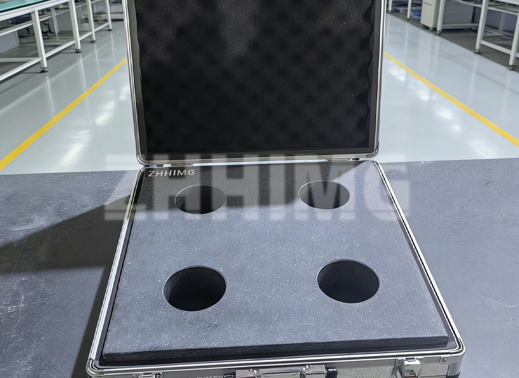
Custom granite components can incorporate holes, threaded inserts, guideway interfaces, cable ducts, and mounting features for special-purpose machines.
Thermal Stability Reduces Drift Risk
Temperature variation is one of the most persistent sources of error in semiconductor inspection.
A machine may operate in a carefully controlled cleanroom while still experiencing local heat from linear motors, illumination modules, detector electronics, vacuum pumps, and auxiliary systems. The critical concern is not just the room-air temperature. It is the temperature difference between the granite base, rails, scales, wafer stage, optical components, and inspected wafer.
Granite has a relatively low coefficient of thermal expansion and low thermal conductivity compared with common structural metals. It therefore changes dimension more slowly and transfers localized heat less quickly through a large structure. This can help reduce rapid geometry changes and make long-term thermal stabilization more manageable.
Published data for high-quality precision granite commonly places its thermal expansion coefficient in the approximate range of 4.6–8.0 × 10⁻⁶/°C, although actual values vary by mineral composition and should be confirmed for the selected stone. Granite is also described by precision-machine suppliers as more temperature-stable than steel and cast iron, with low thermal conductivity supporting a slower response to heat input.
Granite does not eliminate thermal drift. A one-sided motor installation, uneven cooling circuit, or direct HVAC stream can still create structural gradients. Good wafer inspection design separates heat sources from critical datums, uses balanced layouts where possible, controls airflow, monitors component temperatures, and allows the system to stabilize before demanding measurement work.
Vibration Damping Supports Faster Inspection
Inspection systems are often asked to move quickly and measure immediately.
After a wafer stage changes direction, the machine structure must settle before the camera, interferometer, laser, or probe can acquire reliable data. A base with poor damping may continue to oscillate after the motion command has ended. This can force the machine to wait longer before collecting the next image, reducing throughput.
Granite has useful natural vibration damping because of its dense mineral structure and mass. It can help reduce the transmission and persistence of vibration from stage motion, nearby equipment, and floor disturbance. This is one reason granite is used in metrology, semiconductor, optical, and laser equipment where stable positioning matters.
The actual result depends on the complete system. Rail preload, carriage stiffness, moving mass, motor force, cable routing, enclosure design, support feet, and floor characteristics all contribute to settling behavior. A granite base should be selected as part of the machine’s dynamic design, not treated as an isolated improvement.
Customization Matters More Than Size
A larger granite block is not necessarily a better wafer inspection base.
The structure must have enough thickness, suitable cross-section, controlled support points, and correctly positioned interfaces for the specific motion system. It should also be practical to manufacture, inspect, transport, install, and service.
At ZHHIMG®, custom granite bases can be developed for wafer inspection, AOI systems, optical metrology, laser equipment, industrial CT, X-ray inspection, CMM-related structures, and precision linear-motion platforms. The engineering discussion normally includes:
- Wafer size and required inspection travel
- Rail type, linear-motor arrangement, encoder location, and stage mass
- Required rail-seat geometry and datum structure
- Threaded insert, dowel-hole, and mounting-interface layout
- Static loads, moving loads, acceleration forces, and center of gravity
- Operating temperature range, heat sources, cooling routes, and cleanroom requirements
- Required flatness, straightness, parallelism, perpendicularity, and positional tolerances
- Inspection reports, calibration expectations, handling method, and export packaging
Large precision granite bases can be matched to advanced motion systems, with three-point support arrangements helping accommodate non-flat installation tables while reducing unwanted base deformation.
Inspection Validates the Structure
A granite base for semiconductor wafer inspection should be inspected according to the features that affect machine performance.
Final inspection may include primary-surface flatness, rail-seat straightness, rail-seat parallelism, height relationship between mounting planes, perpendicularity of optical-column interfaces, insert positions, locating-bore geometry, surface condition, and support-point location. The component should be measured under defined support conditions using calibrated instruments suitable for the required tolerance.
Laser alignment systems, electronic levels, autocollimators, precision indicators, granite reference standards, and dedicated fixtures may be used depending on the component size and target accuracy. The measurement report should link each value to the customer’s datum scheme and acceptance criteria.
A Foundation for Repeatable Inspection
Custom granite bases elevate wafer inspection stability by creating a controlled mechanical reference for the complete machine. They help manage vibration, reduce sensitivity to rapid temperature changes, support accurate guideway installation, and simplify the integration of motion, optics, sensors, and fixtures.
For global equipment builders, the most effective approach is to specify the granite base around the actual wafer inspection process: motion range, accuracy target, heat sources, guideway interfaces, support condition, cleanroom environment, and inspection method.
When those details are engineered together, the granite base becomes more than a heavy support. It becomes a practical foundation for repeatable semiconductor wafer inspection.
Post time: Aug-19-2026