
How to Specify a Custom Precision Granite Machine Base: Dimensions, Inserts, Tolerances, and Inspection
A custom granite machine base is a commitment: once the block is cut, material removed cannot be put back, and every insert, datum, and tolerance in the drawing gets machined into tens of tonnes of stone. That is exactly why a well-specified order moves quickly and produces a base that drops into the machine on first assembly — and why a poorly specified one produces months of drawing revisions. This guide explains, from the manufacturer’s side, what to provide and what to decide: the drawing package, the custom features (threaded inserts, locating bores, rail seats), the tolerances worth specifying, and how inspection and acceptance should be arranged. It reflects how we process custom orders for granite mechanical components at ZHHIMG, where drawings are reviewed in-house before any cutting starts.
What to Provide: The Drawing Package
An effective granite base specification starts with four documents:
- 2D drawings with dimensions and tolerances. The classic deliverable, and still the contract document. Mark the functional surfaces — datums, rail seats, mounting faces — distinctly from non-critical features. A drawing where every surface carries the same tight tolerance does not communicate quality intent; it communicates that nobody made the trade-off decisions.
- 3D CAD files. STEP or equivalent native formats let the manufacturer verify clearances, compute mass and center of gravity for lifting, and simulate insert placement before quoting. For complex bases, the CAD model catches interference problems that 2D views hide.
- Datum definition. State which surfaces are datums and in what order. Granite bases are lapped and inspected against datums — if the datum scheme is ambiguous, every downstream measurement becomes negotiable.
- Load and interface data. Static machine weight, payload, dynamic loads from moving axes, and how the base mounts to the floor or frame (feet, jack mounts, anti-vibration mounts). This determines whether the section is adequate, where support points should sit, and how the flatness measurement must be conditioned.
If your drawings are not yet granite-ready, that is normal — OEM drawings arrive in every state of completeness. Our design and drawing-checking service reviews manufacturability before quoting: insert positions that conflict with internal stress flow, holes too close to edges, tolerances specified tighter than the measurement method can verify, and support geometry that would distort the finished base. Reviewing on paper is cheap; discovering these in stone is not.
Custom Features: Inserts, Bores, Rail Seats, and What to Know About Each
Threaded Inserts
Granite cannot hold threads, so all bolting happens through steel inserts bonded or pressed into machined bores. A granite base with threaded inserts is standard practice — the specification points are: insert size and material (stainless for corrosive environments), depth relative to plate thickness, and expected clamp load. Two design rules prevent most field problems: keep insert edges away from plate edges and corners (edge distance preserves both the insert bond and the granite), and remember that insert bores are machined before final lapping, so their positions must be fixed early. Changes after machining starts are costly — some are impossible.
Locating Bores and Dowel Holes
Ground locating bores (with matching dowels or pins) set the repeatable interface between the base and the machine frame or between granite and metal subassemblies. Specify their positions from a common datum, state whether the bore or the pin is the master, and control perpendicularity — a tilted locating bore misaligns the assembly in ways shimming cannot fix cleanly.
Counterbores and Pockets
Counterbores for bolt heads, pockets for sensors or cable routing, and recessed mounting steps are routine granite features. The design considerations are section integrity (leave enough wall between pockets and edges) and flatness interaction: a pocket’s floor can be finished, but the surfaces around it carry the lapping process, so keep functional datums out of pocket perimeters.
Rail Seats and Guide Mounting Faces
Rail seats are the most demanding custom feature on most bases. Linear guide rails transmit their mounting-surface errors directly into motion, so the seat faces need specified flatness and parallelism relative to each other and to the datum — over lengths that can run to several metres. Specify whether the seat is finished to mate with a particular rail series, and whether the base supplier or the machine builder performs the final rail mounting shimming. Our granite bases for linear motor stages routinely combine rail seats, motor mounts, and cable channels in one machined block — features that must be engineered together, not added one at a time.
Tolerances: Specify What the Measurement Can Verify
Granite geometry is typically specified in four separate families, and conflating them is the most common specification error:
- Flatness of large working surfaces — the headline spec, achieved by lapping and verified against the datum support condition.
- Straightness of long, narrow features such as rail seats and edges.
- Perpendicularity / squareness between datum faces — critical for vertical structures and gantry elements.
- Position and size of machined features — holes, inserts, pockets, slots.
The governing principle: specify tolerances your quality system can verify and your supplier can measure. A tolerance tighter than the agreed measurement method can resolve is not a tighter part — it is a future dispute. Similarly, over-tolerancing non-functional surfaces adds cost without adding accuracy. During drawing review we flag both cases; the goal is a tolerance scheme where every number has a purpose and a measurement path.
The Production and Inspection Flow
Understanding the manufacturing sequence explains why some decisions must be locked early:
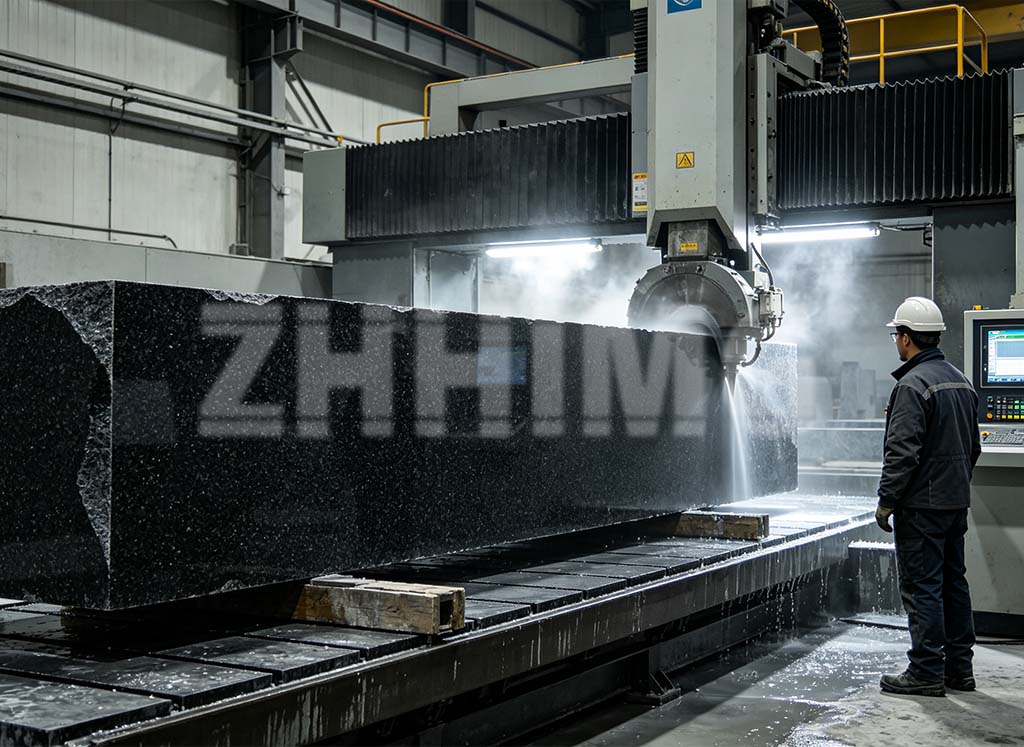
- Block selection and cutting. Raw black granite blocks are selected for the required size; the sawing stage defines the rough envelope. After cutting, dimensions above the finished size are fixed.
- Machining. Milling establishes the reference faces and machines the feature set — insert bores, pockets, slots, rail seats — while the block is in its stable handling condition.
- Insert installation. Threaded inserts are bonded/pressed after machining their bores and before final finishing of functional surfaces.
- Lapping and fine finishing. Hand lapping brings datums and working surfaces to flatness grade. This is the slow, skilled stage — decades of lapper experience show up here — and it is why the flatness numbers on the certificate are earned, not declared.
- Temperature-conditioned inspection. The finished base soaks in the inspection area, then is measured on its specified supports with traceable instruments. The report records instruments, conditions, and measured values per feature.
- Assembly and packaging. Where ordered, subassemblies (stands, metal components, complete granite assembly bases) are built and inspected as units, then packed for transit with edge protection sized to the part’s mass.
What Should Be in the Contract or Technical Agreement
| Clause | What to Fix in Writing |
|---|---|
| Geometry acceptance | Which features, which tolerances, which measurement method and instruments, on which supports. |
| Material | Granite type/grade; density data available on request; substitution requires written approval. |
| Insert specification | Size, material, torque class, and positions — with the drawing revision locked as the order baseline. |
| Inspection report scope | Full report with measured values (not just pass/fail), traceability stated, witness inspection if required. |
| Packaging and delivery | Packaging method for the mass and geometry; responsibility boundaries for shipping; site access constraints for large parts. |
| Revision control | How drawing changes after order confirmation are priced and scheduled — this clause saves relationships. |
One capability note for OEM planners: large monolithic bases require production capacity to match — crane capacity for the block, machining envelope for the finished dimensions, and inspection space for a component that may weigh more than the machine it supports. ZHHIMG’s facility was built around this scale of work, from raw block handling to temperature-controlled inspection of large components, so size limits can be discussed concretely rather than discovered mid-project.
Start With a Drawing Review, Not a Purchase Order
The highest-value step in any custom granite base project happens before the first quote: a structured drawing review against manufacturability, tolerance sense, and inspection verifiability. Send your 2D/3D package, load data, and interface requirements through our contact page, and we will return a manufacturability assessment and quotation with the inspection plan attached. If the design needs iteration — insert repositioning, tolerance rationalization, support redesign — it costs nothing on paper and a great deal in stone.
Frequently Asked Questions
What file formats should I send for a custom granite base quotation?
2D drawings (PDF or DWG) plus a 3D model (STEP preferred). Include datum definition, tolerance scheme, insert specifications, and load/interface data. If your package is incomplete, send what you have — the drawing review will identify what is missing before quoting.
Can inserts be added to an existing base after delivery?
Sometimes, but it is the wrong plan. Adding inserts later means on-site machining or shipping the base back, with flatness risk from re-handling. Design inserts into the first specification; the marginal cost during manufacture is small, and the positions are machined before final lapping.
How tight should I specify flatness on a machine base?
Tight enough for the machine’s accuracy budget and no tighter. Work the budget backward: the motion system, the bearings, and the base each take a share of the error allocation. Over-tolerancing the base beyond what the measurement can verify adds cost and lead time without improving the machine. The drawing review will flag tolerances that are tighter than the verification method.
Do you provide inspection reports with measured values?
Yes — every component ships with a report stating the measured geometry, instruments used, environmental conditions, and traceability. Witness inspection and customer-defined acceptance procedures can be arranged; agree them before production so results are comparable on both sides.
How late can I change the design after ordering?
It depends on the change and the production stage. Before cutting: freely. After cutting and before machining: dimensions can still move with cost impact. After machining insert bores or starting lapping: only minor changes remain possible. This is exactly why the drawing review and the revision-control clause exist — they keep late changes rare and priced fairly.
Post time: Oct-26-2026