
Achieving 0.5 µm-level tolerance on a precision granite component is not a matter of one final grinding pass. It is a controlled manufacturing and measurement process.
For many ultra-precision applications, the requirement is not “0.5 µm everywhere.” That would be impractical and unnecessary for most large granite structures. The requirement usually applies to a specific critical feature: a local rail seat, a precision reference face, a pair of mating surfaces, a guideway interface, a small measuring area, or an assembled datum relationship.
This distinction matters.
A granite machine base may be several meters long and weigh many tonnes, while only selected functional surfaces require sub-micron local control. The rest of the component may have different dimensional and geometric tolerances based on its structural role. A clear drawing, controlled process route, stable environment, and traceable inspection method are essential to producing the right accuracy where it is needed.
At ZHHIMG®, precision granite machining combines material selection, large-format CNC processing, grinding, hand lapping, controlled inspection, and custom assembly. The objective is not to make exaggerated accuracy claims. It is to produce granite components that meet the agreed functional tolerances for CMMs, semiconductor equipment, laser systems, air bearings, optical inspection, precision motion platforms, and custom metrology fixtures.
It Starts With the Right Granite
Granite quality is not defined only by color.
For precision applications, the material should be dense, structurally uniform, free from major cracks or unstable inclusions, and suitable for the required machining and lapping process. Natural variations exist between quarry sources and even within large blocks. Material selection is therefore the first control point.
Incoming stone is checked before it becomes a precision component. The manufacturing team reviews block dimensions, visible structure, grain consistency, and suitability for the planned component geometry. Large components may require careful orientation of the stone block to avoid placing natural features in critical rail seats, thin walls, or high-load mounting zones.
The selected granite is then cut to a rough blank size with enough machining allowance for later grinding and lapping. This allowance is important. Removing too much material too quickly can create unnecessary process difficulty, while leaving too little material may prevent the final surface from reaching the required geometry.
For precision granite, material stability, flatness potential, vibration damping, low thermal response, and surface quality are all linked to the stone selection and the intended application. Granite surface plates and similar measuring surfaces rely on a fine-grained, stable stone structure to create a reliable datum for dimensional inspection.
Rough Machining Establishes the Geometry
The first machining stages create the overall shape.
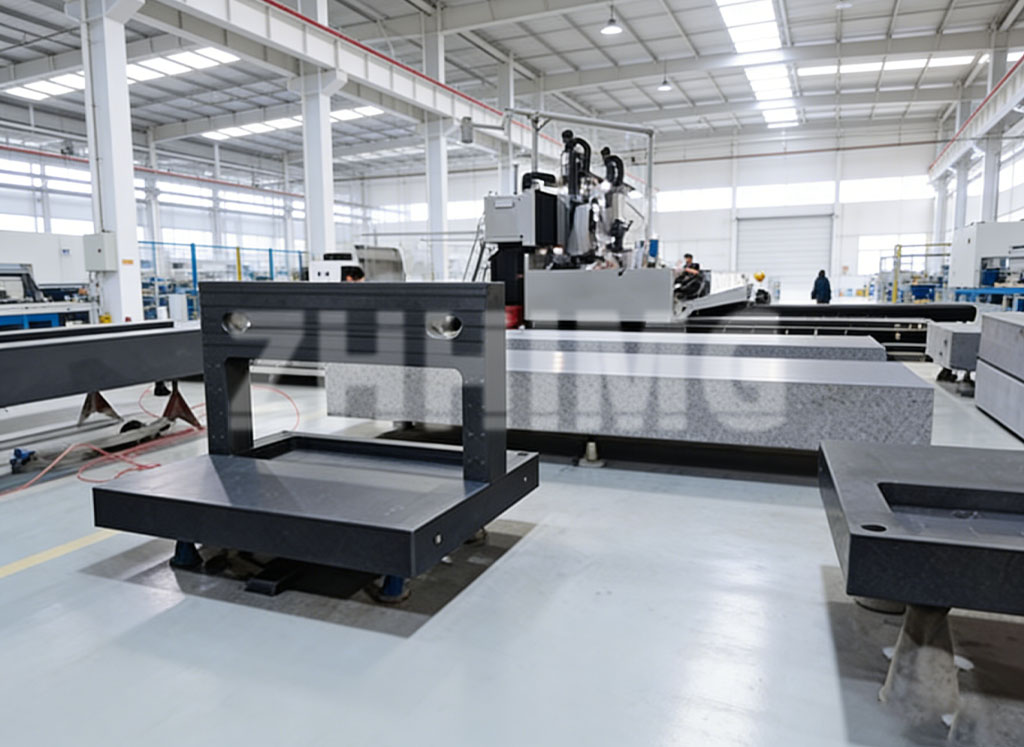
Large CNC equipment cuts the granite blank into the required base, beam, bridge, column, square box, guideway support, air-bearing element, or custom assembly component. Typical operations include surface machining, edge preparation, slots, pockets, holes, recesses, cable channels, mounting faces, and locations for threaded inserts or dowel holes.
At this stage, the purpose is to establish structural geometry and leave controlled stock for precision finishing. The component is not yet a metrology reference.
The machining sequence is planned around the component’s datum structure. A primary reference face is usually created first. Secondary and tertiary surfaces are then machined relative to that established datum. For a granite machine base, the important features may include rail-seat planes, motor interfaces, encoder locations, vertical support faces, insert patterns, and mounting bores.
Large-format components require special attention to support and handling. A long granite base can bend slightly under its own mass if it is supported incorrectly. The same engineering support points must be considered during machining, inspection, transport, and final installation.
Grinding Produces Controlled Precision
Grinding removes machining marks and brings surfaces closer to their required dimensional and geometric condition.
For large granite components, precision grinding is used to control flatness, straightness, parallelism, perpendicularity, and overall dimensions. The process may involve several passes with progressively finer abrasives. Between passes, the component is checked to confirm that the correct material is being removed and that critical datum relationships are being maintained.
Grinding is essential, but it has limits. Typical precision grinding can produce excellent machine-base geometry, yet it may not provide the final local flatness or surface quality required for the most demanding metrology interfaces. Lapping is normally used when the component requires finer correction.
Industry guidance notes that conventional precision grinding commonly achieves flatness in the micrometre range, while lapping is used to refine flatness further through controlled removal of very small amounts of material.
Hand Lapping Makes the Final Difference
Lapping is the stage most closely associated with ultra-precision granite surfaces.
A skilled technician uses a lapping plate, abrasive compound, controlled contact pattern, and repeated measurement to remove extremely small amounts of material. The process is gradual. It corrects high points and improves the relationship between the granite surface and the target reference plane.
Unlike aggressive machining, lapping is a correction process. It can remove sub-micron amounts of material at a time. The operator does not simply polish the surface; the objective is to control geometry.
For a large granite surface, the technician may work in measured zones, repeatedly checking the surface map and adjusting the lapping pattern. A local high point may require attention without disturbing the surrounding reference area. A rail mounting face may need straightness along its full length while maintaining local contact conditions beneath the rail.
Granite surface table re-lapping uses abrasive compounds to remove sub-micron material and restore the working surface to its required flatness tolerance. The same principle applies during manufacturing, although the process route is defined by the component drawing and required acceptance criteria.
Hand-lapping experience remains valuable because the final correction often depends on interpreting small changes in measurement data and surface contact behavior.
0.5 µm Must Be Defined Clearly
A 0.5 µm tolerance should never appear on a drawing without context.
The customer and manufacturer should confirm exactly what the requirement controls:
- Flatness of a defined local surface area
- Straightness along a specified rail path
- Parallelism between two short functional planes
- Height difference between adjacent mounting pads
- Position of a feature relative to a datum
- Local surface condition beneath an air bearing or optical fixture
- Repeatability of an assembled interface
The drawing should also define the measurement length, evaluation area, datum system, support condition, temperature, inspection method, and acceptance rule.
For example, a 0.5 µm local flatness requirement over a 100 mm functional area is very different from a 0.5 µm total flatness claim over a 3,000 mm machine base. The latter would require exceptional design, environmental control, inspection capability, and clear agreement on how the measurement is performed.
High-grade granite surface plates can achieve overall flatness in the low-micron range, with local tolerances depending on plate size, grade, and applicable standard. Grade 00 products are commonly used for laboratory-level reference work and require controlled grinding, lapping, stabilization, and verification.
Inspection Is Part of Production
A 0.5 µm-level feature cannot be verified using an ordinary workshop check.
The inspection method must have appropriate resolution and uncertainty. Depending on component size and feature type, ZHHIMG® may use calibrated Mahr indicators, Mitutoyo instruments, electronic levels, roughness testers, laser interferometers, reference straightedges, granite standards, and dedicated inspection fixtures. For critical applications, the equipment, method, support condition, and inspection record should be agreed before production begins.
Flatness can be measured through mapped point data, electronic levels, autocollimators, laser-based methods, or optical interferometry for suitably sized surfaces. Interferometric methods can provide nanometre-scale sensitivity for small optical-quality surfaces, while long machine structures often require laser and level-based measurement techniques.
Inspection should confirm not only the final value but also the functional relationship between surfaces. A rail seat can be flat but not parallel to its opposite rail. An insert can have the correct thread but be incorrectly positioned relative to the machine datum. The report must reflect what the customer actually needs to assemble and operate the equipment.
Precision Is a Controlled System
Machining precision granite to 0.5 µm-level critical tolerances requires more than advanced equipment. It requires suitable stone, sensible component design, controlled machining allowance, precision grinding, skilled lapping, stable measurement conditions, calibrated instruments, and a clearly defined acceptance method.
For customers sourcing custom granite components, the best RFQ includes a 2D drawing, 3D model, identified critical features, datum scheme, tolerance zones, operating environment, inspection requirements, assembly interfaces, quantity, and delivery destination.
The result is not merely a polished granite part. It is a verified structural reference designed to support the accuracy of the machine built around it.
Post time: Aug-18-2026