
Most questions we receive about threaded inserts in granite machine bases come from assembly engineers rather than buyers. The stone itself is rarely the concern; the connection points are. Will the guide rail bolts line up? Which thread should a sensor bracket use? Can a lifting point take the load? This article walks through the five questions that decide whether a granite base with inserts assembles smoothly on your production floor, and it ends with a confirmation checklist you can use before placing an order.
1. Where Inserts Are Used in a Granite Base
In the bases we build, steel inserts typically serve these connection positions:
- Linear guide and scale mounting: bolt positions along rail seats, usually at defined intervals.
- Drive and motor units: brackets for motors, gearboxes and air bearings that need higher clamping loads.
- Sensors and limit switches: small inserts for brackets that are often repositioned during commissioning.
- Cable management: inserts for ducts, clips and covers along cable routes.
- Handling: lifting and levelling points, including inserts for eyebolts and levelling mounts.
Each of these positions sees a different combination of load direction, tightening access and accuracy requirement, which is why we treat insert design as part of the machine concept rather than a drilling plan added at the end.
2. What to Confirm Before Design Starts
Before we position a single insert, we ask for the fastener and loading information that the assembly will actually see:
- Fastener specification: thread size and pitch, bolt strength class, and whether the joint is threaded into the insert or uses a through-bolt with a nut plate.
- Load case: static weight, moving mass, cutting or acceleration forces, and the direction of each load relative to the insert axis.
- Access and tooling: which side the bolt is tightened from, and whether assembly tools need clearance around the insert.
- Environment: cleanroom compatibility, exposure to coolants or cleaning agents, and any insulation or grounding requirement between the steel insert and the machine frame.
When customers tell us the fastener and the load case together, we can propose the insert type and embedding method that suits the position, instead of defaulting every hole to the same detail.
3. How Insert Positions Are Shown on Drawings
A granite base drawing is easiest to read when insert positions are dimensioned the same way your assembly team will measure them:
- Datum-based positioning: insert centres referenced to the same datums as the mounted component, not to the stone edge.
- Thread callout with depth: size and pitch, usable thread depth, and drill depth shown separately.
- Interface relationship: the distance between the insert pattern and the machined rail seat or reference face it serves.
This matters most for mounting linear guides on granite, where the bolt pattern belongs to the rail, so we dimension inserts from the rail seat datums and verify them in that state.
4. How Insert Positions Are Checked in Production
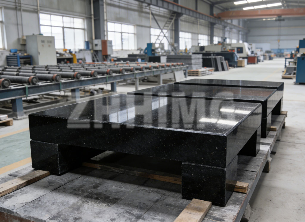
During production, insert quality is controlled at three points. First, positions are laid out and machined against the drawing revision, with the base sitting on the same supports used for final inspection. Second, after the inserts are set, we check position and height with the agreed measuring method, and record the results. Third, for critical patterns we trial-fit the customer’s fastener or a gauge bolt, so the first assembly attempt on your floor is not the first time the parts meet. The photo below shows black granite bases in the workshop at this stage, after insert work and before packing.
5. What to Confirm Before Shipment
Before a base leaves our factory, the following points are confirmed with you so that acceptance at your end is quick:
- Thread check result: every insert passes a gauge bolt or threaded plug gauge check.
- Position report: insert coordinates recorded against the drawing revision you released.
- Protection: threads cleaned, lightly oiled and capped, so no machining dust enters during transport.
- Interface summary: which inserts belong to which mounted component, provided with the inspection documents.
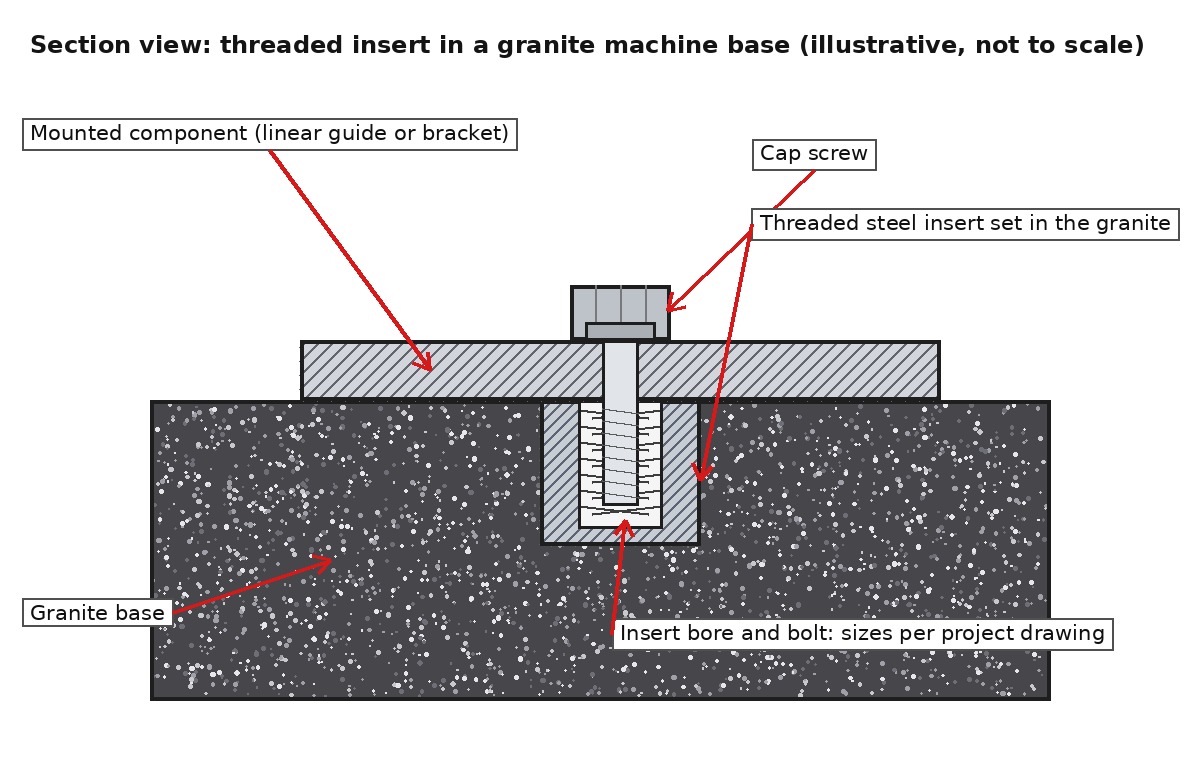
The section drawing below shows the parts of a typical insert connection and how they relate to each other.
6. Insert Design Confirmation Checklist
Copy this list into your enquiry and confirm each row; it covers the points that decide whether the inserts we build will match your assembly process.
| # | Item to confirm | Why it matters |
|---|---|---|
| 1 | Thread size, pitch and depth per position | Matches your fasteners and clamp loads |
| 2 | Insert type and embedding method | Suited to load direction and position access |
| 3 | Load case: static, moving and peak forces | Determines insert size and spacing |
| 4 | Datum for position dimensioning | Keeps drawing, machining and assembly consistent |
| 5 | Tightening tool access and torque value source | Torque is stated on the project drawing, not assumed |
| 6 | Gauge or trial-fit requirement | Confirms assembly before shipment |
| 7 | Report format for position and thread checks | Defines the acceptance documents |
| 8 | Corrosion protection and thread capping | Inserts arrive clean and ready |
A note on numbers: pull-out capacity and tightening torque depend on the insert type, the embedding method, the granite grade and the load direction. We do not quote universal values. For each project, the torque and load figures are stated on the released drawing, and where a position is critical we validate the detail under the specific test conditions agreed with you, then report the result alongside the delivery documents.
7. Working From Your Mounting Layout
Send us your mounting layout, the fastener list and the loads each connection will see. Our engineers will propose the insert pattern and machining concept, return a drawing for your confirmation, and build the base with the position and thread checks described above.
Send your mounting layout and fastener requirements for a review of the granite base interfaces.
Post time: Oct-09-2026