
A precision granite machine base needs more than accurately finished reference surfaces. It also needs mounting interfaces that match the components, loads, and assembly procedures of the machine.
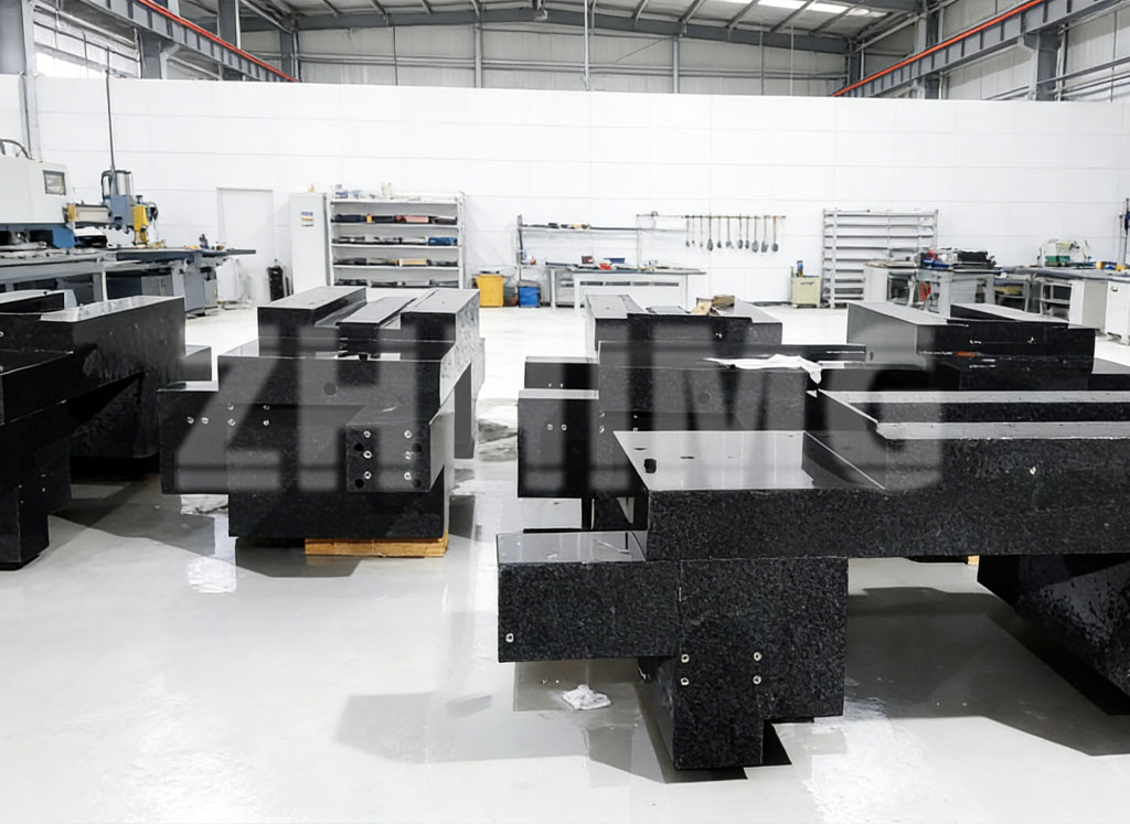
Threaded inserts provide fastening points for equipment mounted to the granite structure. ZHHIMG® offers custom granite bases with bonded metal inserts, including metric or imperial threads and mounting layouts defined by customer drawings.
However, choosing a thread size is only one part of the specification.
Before releasing a drawing, the equipment designer and granite component supplier should agree on the insert arrangement, surrounding geometry, installation condition, loading requirements, and inspection scope.
This guide provides a practical checklist for that discussion. It is not a universal installation standard: allowable loads, tightening torques, spacing, and edge distances must be confirmed for the actual design.
Quick Design Review Checklist
| Review item | What to confirm |
|---|---|
| Thread specification | Metric or imperial thread, pitch, and required engagement |
| Insert configuration | Material, type, external geometry, and installation method |
| Loading | Load magnitude, direction, operating conditions, and verification requirements |
| Surrounding geometry | Distance to edges, openings, pockets, and adjacent inserts |
| Positioning | Datum references, hole coordinates, and positional requirements |
| Mounting condition | Flush, recessed, or another agreed arrangement |
| Fastener selection | Bolt length, engagement, and clearance |
| Assembly procedure | Tightening requirements, access, and installation sequence |
| Inspection | Thread checks, position checks, surface checks, and any agreed load testing |
| Supply scope | Granite component only or an assembled and inspected structure |
1. Start with the Function of Each Mounting Interface
Before selecting an insert, identify what the connection must accomplish.
A mounting point for a cable bracket does not necessarily have the same requirements as a connection supporting a motion assembly. Both may use threaded fasteners, but their functional and inspection requirements can differ.
For each mounting pattern, identify:
- The component being attached.
- The mating surface and hole pattern.
- The expected loading.
- The alignment requirements.
- Whether the component will be removed regularly.
- Any assembly or maintenance access restrictions.
ZHHIMG’s custom granite base designs can incorporate interfaces for linear rails, brackets, covers, precision stages, cable fixtures, and other equipment. The insert layout should therefore be reviewed as part of the machine assembly rather than as an isolated hole pattern.
Where several mounting patterns appear on one base, label their functions on the drawing or in an accompanying interface document.
2. Specify the Complete Thread Requirement
Descriptions such as “threaded hole” or “M8 insert” may leave important details unresolved.
An RFQ should define the thread designation and any additional requirements needed to select the insert and mating fastener.
Information to provide includes:
- Metric or imperial thread standard.
- Nominal thread diameter.
- Thread pitch or threads per inch.
- Required usable engagement.
- Thread tolerance or fit requirement, where applicable.
- Inspection requirements.
- Whether the mating fastener has already been selected.
ZHHIMG supplies custom granite plates with bonded steel inserts in metric or imperial threads, with custom insert types available for review.
Do not treat the nominal thread size as a complete connection specification. The supplier also needs information about the insert configuration, available installation space, and intended loading.
3. Define Loads and Tightening Requirements Together
“How much load can this insert carry?” does not have one answer that applies to every granite component.
ZHHIMG’s product guidance states that insert capacity depends on the thread size, insert type, embedment depth, and surrounding stone. It asks customers to provide the load and its direction so that the arrangement can be evaluated.
A useful design submission identifies:
- Load magnitude and direction.
- Whether loading is static, repeated, or associated with machine motion.
- Any expected overturning moment at the assembly interface.
- Required fastening or tightening conditions.
- Any project-specific verification or acceptance requirement.
The base supplier should also know whether the connection is intended to support equipment during normal operation, transport, or another defined condition.
Do Not Substitute a Generic Torque Table for Approval
If your assembly documentation specifies a tightening torque, submit it for review with the insert design.
Avoid assuming that a torque value selected for a bolt in a conventional metal component is automatically suitable for the complete insert-and-granite connection.
The approved value should relate to the actual interface, fastener, installation method, and load requirements—not thread diameter alone.
4. Review Insert Position Relative to Edges and Openings
A hole pattern may fit within the external dimensions of a base while still requiring further review.
The supplier needs to understand the geometry around each insert, including nearby:
- External edges.
- Large through-openings.
- Pockets and recessed areas.
- Steps between surfaces.
- Other inserts.
- Cross-holes or access channels.
- Thin sections within the component.
ZHHIMG offers granite structures combining mounting inserts with large openings, steps, pockets, and other machined features. Reviewing these features together is therefore important when developing a custom component.
Do not apply an unsupported universal rule such as “all inserts must be a fixed distance from the edge.” The acceptable layout must be evaluated for the specific insert, component geometry, and loading.
If the available space is restricted, ask the supplier to review alternatives before freezing the mating component design.
5. Separate Fastening Requirements from Positioning Requirements
A drawing should explain both how a component is attached and how its final position is established.
If the assembly includes locating bushings, dowel interfaces, reference shoulders, or other alignment features, show these separately from the threaded fastening pattern.
ZHHIMG’s published mounting interface options include threaded inserts, locating bushings, dowel holes, and steel plates. These features can be considered together during the design review.
For each interface, clarify:
- Which features establish location.
- Which surfaces define the assembly reference.
- Which fasteners secure the component.
- Which adjustments are expected during alignment.
- Which relationships will be checked after assembly.
This avoids leaving the supplier to infer the intended alignment method from the threaded hole pattern alone.
6. Define Insert Location from Clear Datums
Accurate coordinates are useful only when the drawing clearly identifies their reference.
For an insert pattern, specify:
- The datum system.
- Hole center coordinates or an unambiguous dimensioning scheme.
- Required positional tolerances.
- The applicable drawing revision.
- The relationship to locating features and precision surfaces.
- Whether requirements apply before or after assembly.
Also distinguish a nominal CAD layout from a controlled manufacturing requirement.
If the 3D model and 2D drawing differ, resolve the discrepancy before production. A consistent drawing package is particularly important when a base contains several mounting patterns for different suppliers’ components.
ZHHIMG’s pre-production review includes datum surfaces, insert locations, hole depths, critical tolerances, and inspection requirements.
7. Specify the Insert’s Relationship to the Mounting Surface
The vertical position of the insert should not be left to assumption.
Depending on the application, a drawing may call for a flush, recessed, or otherwise defined installation condition. ZHHIMG lists flush and recessed mounting conditions among the details that can be specified for a custom interface.
The drawing or interface specification should explain:
- Which surface the attached component seats against.
- The required insert position relative to that surface.
- Any local clearance or relief.
- Relevant surface requirements around the insert.
- How the completed interface will be inspected.
Where a precision mounting face is involved, review the installation and finishing sequence with the supplier. Agree on the condition in which the final surface and insert position will be accepted.
8. Check Bolt Length and Usable Engagement
A matching thread designation does not confirm that the selected bolt length is suitable.
Before approving the assembly, document the relevant stack-up:
| Item | Information to check |
|---|---|
| Attached component | Thickness at the fastening location |
| Washers or spacers | Type and installed thickness |
| Insert position | Flush, recessed, or another specified condition |
| Usable thread | Agreed usable engagement depth |
| Fastener | Thread designation and selected length |
| Clearance | Available space at the end of the fastener |
Ask the supplier to confirm the usable thread condition rather than inferring it from the total insert length or drilled-hole depth.
The installation drawing should then identify the approved fastener and tightening procedure. If different bolt lengths are used on the same base, make their locations clear in the assembly documentation.
9. Agree on Inspection Before Production
Inspection should confirm the requirements that the buyer and supplier actually agreed—not an undefined promise that the inserts are “high precision.”
Depending on the project, the inspection plan may include:
- Insert quantity and identification.
- Thread verification.
- Insert center positions.
- Insert position relative to the mounting surface.
- Relevant datum relationships.
- Surface condition around mounting locations.
- Assembly alignment checks.
- A specifically defined load test, if required and agreed.
Do not assume that a standard dimensional report includes torque verification, pull-out testing, or other mechanical validation.
If such testing is required, define the test conditions, acceptance criteria, documentation, and whether it applies to a representative sample or the delivered component.
ZHHIMG provides inspection documentation and measuring-equipment calibration information as part of its published quality-control scope. The exact report package should be confirmed for the order.
10. Confirm Whether You Need a Component or an Assembly
The project scope may stop at an inspected granite base, or it may include installation and alignment of additional hardware.
These are different deliverables.
A clear purchase specification should state:
- Which components the supplier provides.
- Which components the customer provides.
- Which parts are installed before shipment.
- Which assembly relationships must be inspected.
- Which adjustments remain for installation at the customer’s facility.
- What final documentation is required.
ZHHIMG offers assembly, calibration, and inspection with customer hardware, including linear guides, subject to the agreed project requirements.zhhimg
If assembly is included, submit the mating component drawings and part numbers early. Reviewing the granite base without the corresponding hardware information can leave important interface questions unresolved.
Common Specification Gaps to Resolve Before Ordering
A Thread Callout Without a Load Requirement
The supplier knows the nominal thread size but not what the connection must do.
Provide the intended loading and fastening requirements alongside the thread specification.
A Hole Pattern Without a Datum Plan
The coordinates are shown, but their relationship to the machine’s functional references is unclear.
Identify the relevant datums and locating features.
Insert Positions That Ignore Nearby Features
The insert layout is reviewed separately from openings, pockets, or stepped sections.
Review the complete local geometry rather than the hole pattern alone.
Bolt Length Selected Before the Interface Is Confirmed
The fastener is chosen without checking the mounting stack and usable thread.
Confirm the interface dimensions before releasing assembly hardware.
An Inspection Request Added After Production
The buyer expects checks that were not included in the quotation or manufacturing plan.
Agree on inspection and reporting during the RFQ stage.
What to Include in Your RFQ
For a granite base with threaded inserts, send the following information:
| Category | Details |
|---|---|
| Application | Equipment type and function of the base |
| Drawing files | Dimensioned 2D drawing and available 3D model |
| Revision | Current drawing and CAD revision |
| Base geometry | Overall dimensions, steps, pockets, and openings |
| Datums | Reference surfaces and locating method |
| Thread pattern | Sizes, quantities, coordinates, and tolerances |
| Insert requirements | Material, type, position, and usable engagement |
| Loading | Load magnitude, direction, and operating conditions |
| Assembly | Mating components, fasteners, and tightening requirements |
| Inspection | Required checks, reports, and agreed testing |
| Quantity | Prototype and repeat-order requirements |
| Delivery | Destination and requested schedule |
If some requirements are still being developed, identify them as open items. That allows the supplier to separate preliminary assumptions from approved production requirements.
Frequently Asked Questions
Can threaded inserts be incorporated into a custom granite machine base?
Yes. ZHHIMG manufactures granite bases with bonded metal threaded inserts and other mounting interfaces according to project requirements.
Are metric and imperial threads available?
ZHHIMG’s custom granite plate offering includes metric and imperial threaded inserts. Specify the complete thread designation and required engagement in the inquiry.
What is the maximum load for an insert in granite?
There is no single load rating for every design. Capacity depends on factors including the insert type, thread size, embedment depth, and surrounding stone. Submit the loading and geometry for review.
What tightening torque should be used?
Use a project-approved requirement for the actual connection. Thread size alone is not enough to define an acceptable tightening torque.
Can locating features be included alongside threaded inserts?
Yes. ZHHIMG lists locating bushings, dowel holes, steel plates, and other mounting interfaces among its custom options. Their functions and datum relationships should be defined on the drawing.
Can an existing insert be replaced or modified?
Request a case-specific assessment before carrying out any work. Provide the existing insert details, component drawing, condition, and intended modification. Do not assume that a repair or thread change is acceptable without review.
Request a Design Review for Your Granite Mounting Interfaces
A well-defined mounting interface brings together the granite geometry, insert design, mating component, fastener, and inspection plan.
ZHHIMG® supplies custom precision granite bases with threaded inserts, machined mounting faces, openings, and locating interfaces defined around customer drawings.
To discuss your project, send:
- Your granite base drawing and available CAD model.
- The mating component or mounting pattern.
- Thread specifications and insert quantities.
- Loading and tightening requirements.
- Critical positioning and surface requirements.
- Inspection and assembly expectations.
Define the connection as carefully as the reference surface. Both belong in the design review before production begins.
Post time: Nov-06-2026